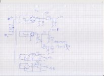
Similar topology driver for fix biased 300B PP.The topology -maybe- would be similar.

It's NOT MH-300B, only sample for possible driver!

They are waiting for someone to send the schematic.......should we see something like this happen?
Thanks for all the answers. I haven´t had the amp inhouse yet, but I expect to have it today. Unfortunately it seems only the missing resistors are with the amp, but still I think it would be a job that can be done with all the inputs. There are only so many ways to make a Push Pull amp with these tubes. I am looking forward to the challenge..
It will be very interesting to see, how the resistors match the values in this schematic.Similar topology driver for fix biased 300B PP.
View attachment 1325708
It's NOT MH-300B, only sample for possible driver!
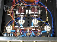
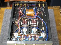
Here is the picture of the MH-300B with a lot of components removed. My friend forgot to bring with him the bag of resistors , that presumably should go into the amp. Capacitors are missing too, but my friend didn not get any from the so called "tech"..
I haven´t yet drawn any preliminary schematic, it is vacation time around here..😀
I haven´t yet drawn any preliminary schematic, it is vacation time around here..😀
Well, the good news is you now have a fabulous platform to implement a variety of different push-pull input circuits. And the filament circuitry for the 300b tubes seems to be intact.
But, he's removed all components from the 3 sockets in the middle of the amp. That was your preamp/driver/phase splitter section. It's impossible to say how those 3 tubes were configured, so you'll either have to wait to hear back from the manufacturer, find a schematic online, or start experimenting.
This listing has some gut shots, but they're messy.
Last edited:
I am quitté sure I can figure out , how it is configured, as it is much the same as ma 300b
The filament supply is obviously tampered with on purpise and compléterly wrong. There is a Strange Thing around the level control, as the returnere on the potmeters are connrcted to the - Bias supply
The filament supply is obviously tampered with on purpise and compléterly wrong. There is a Strange Thing around the level control, as the returnere on the potmeters are connrcted to the - Bias supply
These are not the same schematics. It is a bit unusualIt will be very interesting to see, how the resistors match the values in this schematic.
This would not work well. A long tailed pair phase splitter must have a high resistance as common chatode resistance to work properly. In this amp, the button of the potmeter is connected to the negative supply that is used for biasing the 300b's. This is probably done so that the anode resistors can be made equal. Furthermore there is a wire connected in each channel from the negative supply to the terminal strip behind the tubes and I guess this is used as the termination of the common chatode resistor, so that the resistance can be high enough for the long tailed pair to work properly. I am in a summer cottage right now, so this is all from memory and I cannot investigate further until I get home again.
The reason why your schematic wouldn't work is that the grids are @ ground potential so the voltage from chatode to its return (in your schematic : ground) is too low for a high resistance common chatode resistor.
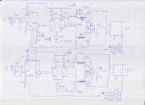
I found two pretty good pictures of Mactone MA300B and comparing them with what was left in the Mactone MH 300B I could make a schematic that , I think , is pretty much how the amp is made. Apparently the two ; MA300B and MH300B share the same schematic.
As you can see, they have designed the phasesplitter/driver a little different, because they make use of the negative supply from the 300B bias circuit to make a small negative grid bias and a higher negative voltage return for the common cathode resistor in the long tailed pair. As I see it , they thereby can use equal anode resistors and still keep balance and they can have a high value cathode resistor without sacrificing voltage swing out of the driver. I am a little surprised by the lack of bias regulating for the 300B's, just a rectified 70V ac Hmmm.
Any comments?
Attachments
- Home
- Amplifiers
- Tubes / Valves
- Mactone MH-300b schematic or photo