So OK, you need to make sure that grid resistor (100k) are all grounded, esp you have auto-bias that will try to correct itself, but the volume level could be affected.
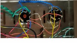
One more snapshot, it appears there is missing/extra wire, see attached.
One more snapshot, it appears there is missing/extra wire, see attached.
Attachments
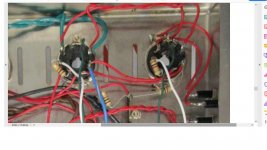
Thanks. The grid resisters look well grounded, but I will resolder them. Sorry but I am not seeing the missing wire you are talking about. The wires connecting pins 1 and 6 (v1 to v3, and v2 to v4) were removed as part of the autobias install. Are these what you mean?
There is an extra red wire (near 1k res) on the left in snap-2, not in your wiring (snap-1). Also you ensure the resistance is about 100k between grid and ground.
Last edited:
Well spotted Knoow. He means there's an orange wire joining the two screen grids. I'm guessing the blue striped wire is off the OPT, what's the orange wire going to the two 100r resistors?
I see a total of 6 red wires running to V-3 (the left socket) in snap-2. The top 2 (pins 2 and 7) are blue in snap-1. The right 2 (pins 3 and 4) are orange in snap-2. The bottom/left 2 (pins 4 and 6) are red in snap-2. Sorry, not seeing the extra wire.
Do you mean pin 3 to pin 3 (where the 100 ohm resister is?) Both pictures show that, don't they?
Wiring diagram (without autobias board): https://www.amazon.com/photos/shared/zzcb6cqyRS-wWHztrtGJYQ.0OayLYIFtQ2N0e0Dvs9llw
If I probe pin 3 and the ground lug the resisters are soldered to, all 8 (4 sockets, 2 amps) read about 50K.
Automatic bias control module for DYNACO M125, AB-Qi-M125 v2.0 with isolation transformer TES
https://www.audioamp.eu/_obchody/te...-pushpull-koncovych-stupnu-pro-dyn-94c713.pdf
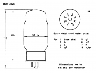
Pin 3 is anode, grid 1 is pin 5. I just couldn't locate the other 2 100k grid resistor, R32, R30.
https://www.audioamp.eu/_obchody/te...-pushpull-koncovych-stupnu-pro-dyn-94c713.pdf
Pin 3 is anode, grid 1 is pin 5. I just couldn't locate the other 2 100k grid resistor, R32, R30.
Attachments
Last edited:
I am really missing this. I asked my son to look at the picture for the missing wire and he does not see it either. Here is a photo showing a red (or orange) wire going to pin 6 in both photos. I drew a crude arrow showing the same wire connection in both.
https://www.amazon.com/photos/shared/hSLbph14TqKUibrH_zAe9w.mIOKrES5leHqZ5tW8BpGJA
https://www.amazon.com/photos/shared/hSLbph14TqKUibrH_zAe9w.mIOKrES5leHqZ5tW8BpGJA
My picture of the board does not do a good job showing R32, R30 (bad angle) I have double checked this - and will check again - to make sure they are well-soldered to the correct place on the board.
Why the white wire is not there: From the autobias instructions:
1. Remove the two 10 OHM bias resistors connected to pins 1&8 on the two output tube sockets,
marked with a RED X on the photo
2. Remove the wires, marked in white on the above photo, between pins 1 of the tube sockets for
V1 to V3 and V2 to V4
3. Remove the wires, marked in white on the above photo, between pins 6 of the tube sockets for
V1 to V3 and V2 to V4
One of wire (either red or white) on Pin 6 should be connected to grid resistor 100k (according to schematic). I have no idea, you already confirm it is 100k between all grid1 and ground?
Thank you for your help, I appreciate it very much. I think you are asking me to measure resistance between pin 5 and ground. My reading is 5.4 M
On the wiring diagram from the M-125 instructions which I posted earlier, there is no wire between pin 6 and the grid resister. The grid resister is 100 ohms, not 100K ohms.
For pin 6:
- it shows v3 out and v4 out from the driver board going to v3 and v4 respectively.
- V3 and V1, and V2 and V4 tied together (removed per autobias)
- the IK resister between pins 5 and 6.
No other connections to P6
The 100 ohm resister connects to pin 3. Per the wiring diagram pin 3 (V3 and V4) have connections from the output transformer (blue and striped blue wires) and a connection P6 to P6 to both V1 and V2.
No no..100 ohms is anode resistors. R32, R30 and R32B, R30B are grid 1 resistors 100k, I can see R32B, R30B on auto bias module. You have all the 4 missing or not connected or connected but not ground. The other wire from pin 6 is connected to the coupling capacitor appear to be on auto bias module, otherwise there will no output.
This module appears to be CCS constant current source that limit the tube current (so it does draw too much current even you don't have any grid1 resistor connected). Read the schematic instead of the instruction as there are mistakes..I can't believe that is the right instruction you posted earlier..
This module appears to be CCS constant current source that limit the tube current (so it does draw too much current even you don't have any grid1 resistor connected). Read the schematic instead of the instruction as there are mistakes..I can't believe that is the right instruction you posted earlier..
Last edited:
OK, I understand better what you are saying. R30 and R32 (V3, V4) are on the driver board. R30B and R32B (V1, V2) are on the autobias board. All 4 100K resisters are present. V1 and V2 GRD are connected to R30B and R32B as part of the pcb layout. V3 and V4 GRD connect to the driver board and presumably have the 100K resisters in the path. I need to verify that. V1 out and V2 out are connected tro P6 on V1, V2 respectively.
Exactly where should I measure to determine if the 100K grid 1 resisters are connected?
Exactly where should I measure to determine if the 100K grid 1 resisters are connected?
- Home
- Amplifiers
- Tubes / Valves
- M-125 Monoblock Debugging Advice