And Peufeu is rigth, - both these chips (1656 & 1612) are fast, correct bypassing is needed..?
damn you're giving away the spoilers
with bad layout and DIP adapters I'd use the low-THD low gain bandwidth opamps from TI, not the 50MHz ones. I put OPA1642 in the old TEAC to replace the old turd 4558, it has a very civilized 10MHz GBW, on the single layer board with decoupling caps a mile away, it works great.
Last edited:
My oh my, who should I believe now?
It's probably the close-in phase noise taking away the meaty character of the OPA1656. Or, maybe it's noise modulation creating intermodulation products with the hystersis distortion of the ferrites in the treble region causing the bass to be perceived as less weighty.
Hey.. You are right, absolutely forbidden just listening to music. Problem is, that though I love the green phosphor of my analyzers, I could even closely following them all session - but those fans...
Have a nice time! G
Have a nice time! G
Hey.. You are right, absolutely forbidden just listening to music. Problem is, that though I love the green phosphor of my analyzers, I could even closely following them all session - but those fans
Except for a timepod, has no fans, and always a soothing effect on your ears. And don’t forget to suspend those oscillators using some soft rubber bands, as advised on another topic, the sound would be less coloured by the evil quartz vibrations.
Hey.. You are right, absolutely forbidden just listening to music. Problem is, that though I love the green phosphor of my analyzers, I could even closely following them all session - but those fans...
Have a nice time! G
Don't worry, when you become good enough at it then you can ignore the noise. It's like The Matrix. 😀
Did a subjective listening test at this point with two listeners comparing notes. A little rolling of opamps ranks them in the following order by preference:
1. TI NE5532
2. OPA1612
3. OPA1656
NE5532 was the most balanced tonally with good bass and midrange, and with fairly clean cymbal sounds.
OPA1612 was more 'splashy' on cymbals (more distorted cymbal sound).
OPA1656 gave cleaner cymbals and a lot of detail, but midrange and bass were thin and understated.
Again, this was with Neurochrome HP-1 acting as differential summing amp. Since its input RF filter uses ferrites and I am leery of the possibility of hysteresis distortion, maybe some difference at that point. Sound differences might not be solely due to the opamps is all I'm thinking.
Regarding the dac chip itself, its still too early to tell very much but seems like it might better at reproducing low level room decay sounds than AK4499.
More later.
Well.... no expectational bias there. 🙂
From what I've seen of their let's call it unique grounding scheme, it may be worth implementing an RF 'trap' right on the DAC OP. The I-V's are a long
way from the DAC chip and these current OP DACs are capable of very fast edge rates. Those current loops are large and by the look of it, not well
controlled.
The advantage of current OP architecture is it should tolerate some amount of OP voltage compliance without impact on distortion compared to ESS / AKM super low Z OP.
Given this you might be able to implement say a 500kHz or so low impedance RC LPF right at the DAC OP. At least this could help with keeping the super HF current edge rates contained close to the DAC.
Another thing to try is ditch the PML bypass caps on audio opamps. Yes ... I know (Chris / Syn etc etc) they are there for stability with these wide BW
OPAs but they are also very high Q and that could be a bad combination with this boards crappy ground layout. The small form factor Elna RFS have very
good impedance characteristics well in the MHz range and should be sufficient. Obviously check for stability with a suitably wide BW Cro.
I think ultimately the eval board itself is prolly the biggest hindrance to the DAC's potential performance. I know that sounds crazy but it wouldn't be the first time.
How are your Altium skills progressing?? 🙂 🙂
Thanks for the update. Some of us do appreciate the time you are putting into this.
TCD
Another thing to try is ditch the PML bypass caps on audio opamps. Yes ... I know (Chris / Syn etc etc) they are there for stability with these wide BW
OPAs but they are also very high Q and that could be a bad combination with this boards crappy ground layout.
Actually, I might agree. I, personally, wouldn't use PML caps for bypass/decoupling. Though I doubt this has any audible influence here if the op-amp is stable. Keeping the film cap and adding a > 500 mOhm ESR cap may work too. If it's not oscillating then you probably already know what I think the value of sighted subjective impressions are.
The sighted subjective impressions are correctly telling him that something does not work in the setup..
Terry is suggesting good advice. Though. May I colour a bit? Reality is always a step ahead in complexity. We are forced to use PML / PPS caps at job. Guess what could be the reason for that..
And we use high speed opamps and we need all that GBW. We also can not tolerate not controlled response.
And it is possible, with those pesky film caps..
Zero MLCC is permitted.. Not even a bit of help from them..
(but we can do layout as needed)
Ciao, George
Last edited:
I see no uncontrolled response from LTC6228, ADA4899, ADA4938-2, etc. on my bench with MLCC decoupling. Your job is not audio, anyway. Plenty of critical applications use MLCCs despite the piezoelectric effects. Home audio is not aerospace, defense, or energy. It's a crappy eval board with NE5532, not liquid cooled instrumentation for CERN. Of course, you are blind to context and even for the reason for Terry's comment. Go ahead and use high Q zero ESR film cap decoupling with an inductive layout.
Is your ego that large that you think you are the only person in the world that knows that Class II ceramics are highly piezoelectric?
Is your ego that large that you think you are the only person in the world that knows that Class II ceramics are highly piezoelectric?
Last edited:
On a 4 layer board, +/-15V power planes on L3/L4 make opamps very happy. It is often said that one should put a decap between V+ and V- to soak up class-B output current and prevent it from going into ground through the V+ and V- decoupling caps. I prefer placing the 2 decoupling caps on the same side of the opamp, so they share the ground vias, so class B current goes through the caps and the vias only inject clean current into the ground plane. This also minimizes loop area and magnetic coupling. But this is not the case on this board.

The output currents look like they're high enough to push the opamps into class-AB. So, perhaps a JFET at the output of the opamp, to bias it in class A, would be useful.
They routed the +/-15V on L3 with maximum length, high inductance, skinny traces, and put low ESR film caps at the end. This is the power routing:

I have something to ask of Mark 😀
With the fast opamp mounted, I'd like to see a scope shot of +/-15V. On the furthest opamp from the power entry connector, probed on the opamp power pin (not the decoupling cap, that's cheating) with the probe ground clip set on the closest ground via... Something like 10-100 ns/div to observe supply ringing on transients, if any.
If ringing is observed, an effective fix is to replace the SMD film caps with a smaller MLCC and a tiny 0R47 or 1R resistor in series. The SMD film cap looks like 1206 so a 0805 MLCC and a 0603 or 0306 resistor should fit on the existing pads with a bit of tweezer work. If you solder the resistor upside down, with resistive film against board, that shaves off a slice of a nH, but that doesn't matter here.
I'd also like to know the ESR of these caps:

Since they are "audio" it's probably high enough.
Also due to cuts in ground plane, the return current path from opamp's decoupling caps to DAC GND remains mysterious.
Probing the DAC's power supplies should be interesting. Also, probing between GND at the opamps, and the thermal pad GND vias under the DAC.
The output currents look like they're high enough to push the opamps into class-AB. So, perhaps a JFET at the output of the opamp, to bias it in class A, would be useful.
They routed the +/-15V on L3 with maximum length, high inductance, skinny traces, and put low ESR film caps at the end. This is the power routing:
I have something to ask of Mark 😀
With the fast opamp mounted, I'd like to see a scope shot of +/-15V. On the furthest opamp from the power entry connector, probed on the opamp power pin (not the decoupling cap, that's cheating) with the probe ground clip set on the closest ground via... Something like 10-100 ns/div to observe supply ringing on transients, if any.
If ringing is observed, an effective fix is to replace the SMD film caps with a smaller MLCC and a tiny 0R47 or 1R resistor in series. The SMD film cap looks like 1206 so a 0805 MLCC and a 0603 or 0306 resistor should fit on the existing pads with a bit of tweezer work. If you solder the resistor upside down, with resistive film against board, that shaves off a slice of a nH, but that doesn't matter here.
I'd also like to know the ESR of these caps:
Since they are "audio" it's probably high enough.
Also due to cuts in ground plane, the return current path from opamp's decoupling caps to DAC GND remains mysterious.
Probing the DAC's power supplies should be interesting. Also, probing between GND at the opamps, and the thermal pad GND vias under the DAC.
They routed the +/-15V on L3 with maximum length, high inductance, skinny traces, and put low ESR film caps at the end. This is the power routing:
Wait a minute.. There are those two electrolytics in there, too.. (bypass structure) They should absorb the trace inductance.. With a bit of luck, they are not too low ESR, maybe?
Waiting for measurements lol.
Still got lots of trace length with film caps at both ends, yeah maybe the electrolytic will add some damping. But look at this. The power traces are not routed on ground plane, they have to cross like 4 cuts to get to the opamp... So what is the inductance? Depends on loop area, which means wherever the return current path is in this mess...

> With a bit of luck, they are not too low ESR, maybe?
Don't worry, someone will "tweak" it and put OSCONS
Still got lots of trace length with film caps at both ends, yeah maybe the electrolytic will add some damping. But look at this. The power traces are not routed on ground plane, they have to cross like 4 cuts to get to the opamp... So what is the inductance? Depends on loop area, which means wherever the return current path is in this mess...
> With a bit of luck, they are not too low ESR, maybe?
Don't worry, someone will "tweak" it and put OSCONS
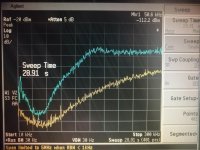
About looking for the ps rails.. I smell some difficulty, there. When I had a look, last year at directly on the 4499 I/V section output, I have found a nice big amount of shaped noise. The pics offer some taste of it (repeating, had shown already).
That, on a scope, looks like.. Noise.. And a lot.
That is the output, but if the opamp has to work that heavy, it will definitely appear on the PS.. And it is still 'correct'...
Maybe it would be better, needed to go for the spectral shape, and search for suspicious looking spurs, extra, etc.. In probable frequency ranges.
Attachments

But look at this. The power traces are not routed on ground plane, they have to cross like 4 cuts
Ouch, You are right
About looking for the ps rails.. I smell some difficulty, there. When I had a look, last year at directly on the 4499 I/V section output, I have found a nice big amount of shaped noise.
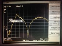
Oh yes there'll be plenty of broadband noise, so if there are underdamped resonances between the caps, or anywhere else, or bad layout/ground, they'll be excited and you get ringing and spikes, which makes it worse. In fact having a lot of sigma delta and digital noise around means layout & decoupling are even more important that for standard analog...

That's the output of ES9023 with ridiculously bad layout (red) and good layout (black) ; in the latter case there's only modulator noise which is unavoidable...
Last edited:
Agree about clocking. Using BCLK for MCLK may be a problem. Not sure if I2SoverUSB processes both with equal care. To run the dac in DSD256 phase mode (normal MCLK) will require programming the registers myself. If really better to run it with half frequency MCLK, perhaps better to use a very cleanly divided MCLK than BCLK. At least for these SD dacs I tend to treat MCLK more carefully than the I2S clocks.
Other factors that I think may be hiding problems could be the capacitive analog output coupling and the AVCC design. Have to see.
Also, agree that there may be trade offs in choice of bypass caps for I/V. SMD film caps are more linear than X7R but the latter is good in other ways.
Actually, I was sort of surprised at the opamp rolling results, but at least now some idea of why they populated the board with TI NE5532 (which I have been told sound better than the JRC version). Probably just a symptom of other problems, would be my guess.
EDIT: Agree about shaped noise coming out of the dac chip analog outputs. The long, wide traces from the dac chip outputs to the I/V opamp inputs could be having some trade off effects too.
Also, opamps are on Brown Dog adapters at the moment. Agree inductance is higher than if SMD mounted right next to decoupling caps. Probably, I should just solder OPA1612 or OPA1656 to the PCB and work on trying to make things sound right that way. Also know I can do much better at the I2S and MCLK input than straight from I2SoverUSB. Take some time to get it all setup though. May want to do a revision of a clock, digital input, and DSP board I made for AK4499. Haven't decided how I am going to do some tests particular to this chip. Scope probing may tell me if there are problems with the board design around the opamps (not unlikely), but I know from lots of time optimizing AK4499 that is hardly going to be the only problem.
Anyway, I also have a couple of loose BD34301EKV chips if I want to make my own board for it. Too soon for that though, I think there are still questions that can be investigated using the eval board.
EDIT 2: Thanks guys for all the thoughtful comments. There are a small few comments not intended to be helpful which I will disregard.
Last edited:
Did a subjective listening test ...
OPA1656 gave cleaner cymbals and a lot of detail, but midrange and bass were thin and understated.
Strange.. OPA1656 in my application sounds meaty, with a lot of weight.
Yup, such is the usefulness of subjective listening test.My oh my, who should I believe now?

A little more progress. I/V opamps at this point are OPA1612 still on adapters. Jumpered the XLR output coupling caps. Routing the output with it's roughly -3v offset into a class-A MOSFET buffer setup to remove DC offset using some pretty good big film caps. The buffer box has been powered down for a few days and the particular film caps in it are ones that can take a couple weeks to fully 'open up.'
For any unfamiliar with the terminology of 'closed in' verses 'opened up,' the former means the sound is a bit dynamically flat and instruments and vocals sound not quite clearly separated from each other dynamically and in small details. 'Opened up' means there is little or none of the 'closed in' sound problem. 'Closed in' doesn't sound like a harmonic distortion issue; possibly it could be a small change in linear distortion. I'll give the system some time and see how things go.
Right now PCM is sounding pretty good. I think my clock and DSP board can probably help clean up the sound some more too. The coupling caps seem to have been a significant sound quality issue.
Did an experiment earlier while playing DSD256 from HQ Player. Noticed I forgot to pull the MCLK pin header connector coming from I2SoverUSB, and jumper BLCK to MCLK going into the dac board. The unit way playing fine with the wrong MCLK frequency, and here is the surprise: It kept on playing just fine with no signal at all going into MCLK. Weird. BLCK must be the main clock in standard DSD mode?
BTW, something sorta like that but different in details is also true for AK4499 and some other AKM dac chips running in DSD mode. MCLK can be double the correct frequency and sometimes they will still seem to play fine. Closer listening with very low distortion gear did show the sound is a little cleaner with correct MCLK frequency.
Something in some way similar may be going on with the Rohm chip. Could be at some point the sound will be cleaned up enough to make any tiny differences more audible.
Last edited:
- Home
- Source & Line
- Digital Line Level
- Luxman uses ROHM Semiconductor MUS-IC BD34301EKV dac