It really is a matter of what you have to hand or is affordable locally. The main functional requirement is not that it is a solvent, but simply a volatile fluid that doesn't attack any plastic materials - it's used here as a flushing agent.Why clean pots with dangerous substances when regular alcohol or IPA works super fine....
Read an MSDS document by Googling one for IPA and industrial or even pure alcohol and you may not be so sure about whether they are much safer.
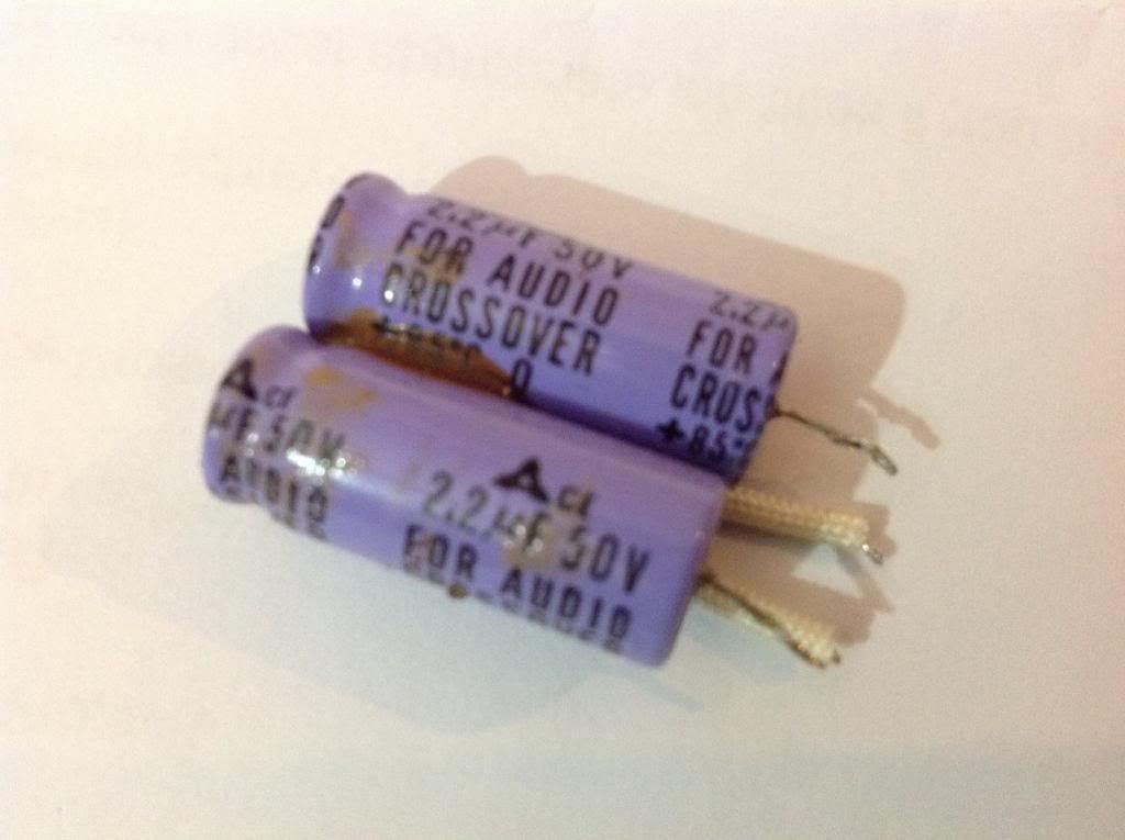
Replaced the el caps with poly extra pair in my parts bin..
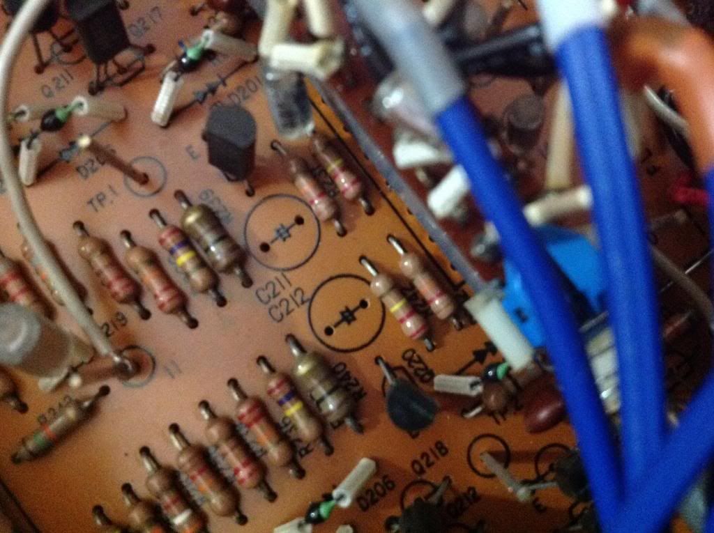
Old caps & location
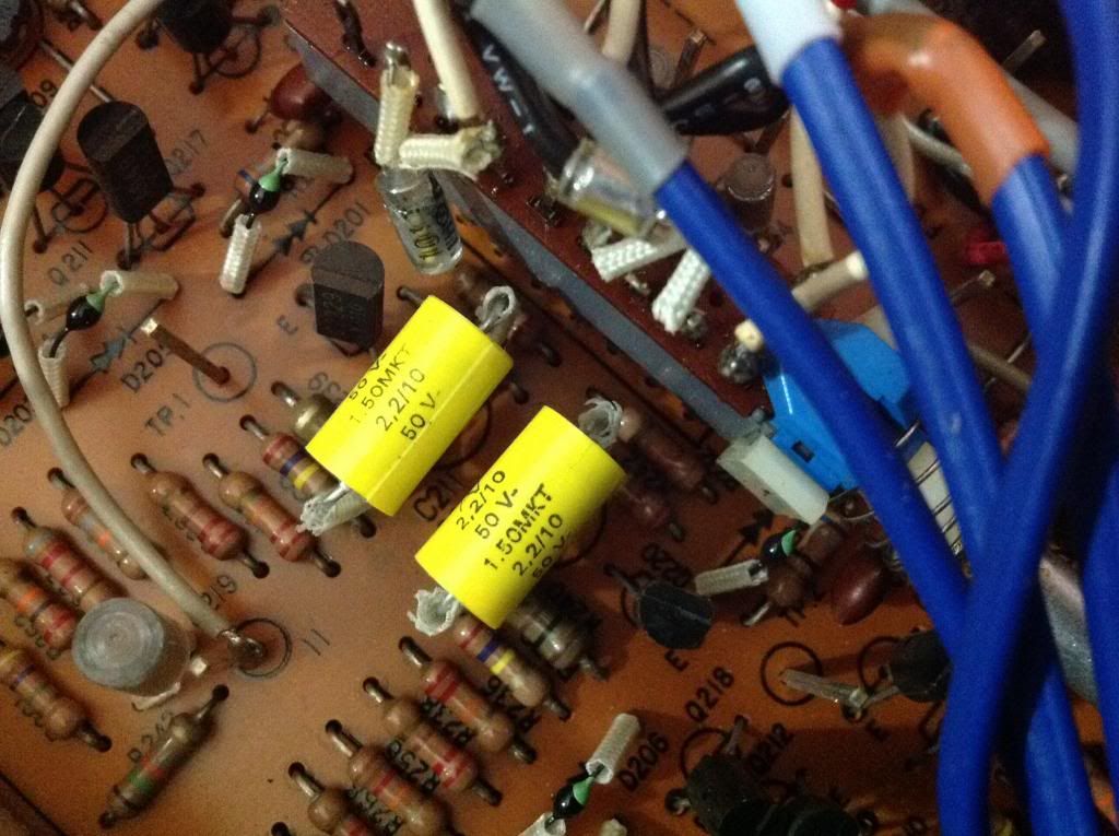
New caps installed
Old caps & location
New caps installed
Ojojunkie, any further progress on the recap? How much difference has it made?
I have a C120A (not the MKII) but the boards look almost identical from the photos. There are three types of caps in it. In the PS and most other electrolytics are Rubycon. Signal path caps are Elna and there are two Marcon caps C223 and C224.
The unit powers up fine, is dead quiet but lacks the presence and detail of my Bottlehead Foreplay II tube pre-amp. After reading a large number of posts on the subject I decided to give the Luxman a new life and another chance with a recap.
Plan is to replace all Rubycons with Cerafines and the Elnas and Marcons with Silmic II's (again signal path).
Why? People seem to like the Silmics for their smoothness and "tube like" sound while others like the Cerafines, and others, for their detail and punch.
As this is a little subjective, I figured it a good place to start plus it seems like a similar mix to stock but hopefully with much improved components -- and with 30 year old caps, it is bound to be an improvement.
I am likely going to do the PS caps first, then the pre-amp, phono and tone section (I usually bypass this - Foreplay has none of it).
I have photos and a spreadsheet showing the existing complement of caps and the proposed compliment. And can post if there is interest.
Hi Dhayes5, the el-caps are the last pair I replaced and begun listening to music. From the PS caps I immediately heard a big improvement/change in SQ. Replacing the caps at signal path refined even more the presentations, music became very detailed form vocal to instruments. Unfortunate have to take the pair off the rack for control and pots cleaning. Now, I'm back to old preamp+amp (B&K) combo setup.
Have the original model service manual which I found some changed of caps values esp. In PS circuit.
Feel free to post all info you have about these gears.
To; AJT, Ian & Welcome, thank you for the infos you shared. All your insights are very valuable for non-tech guy like me. 😛
The units are waiting for my tech fiend to come-by and do the cleaning with right solution. He reminded me not to use any local cleaning fluid that might cause more damage than fix the problem. 🙂
The units are waiting for my tech fiend to come-by and do the cleaning with right solution. He reminded me not to use any local cleaning fluid that might cause more damage than fix the problem. 🙂
Planned C120 Recap
Parts are starting to trickle in. The attachment is an excel spreadsheet showing all electrolytic capacitors in system and what they will be replaced with.
I did also consider poly caps for C211 and C212 but decided to stay with a kind of original Luxman combo.
I have an Adcom GFA555II that this will be mated to and a set of Kef Q75.2 speakers. A friend of mine has also just bought new amps and is giving me a GFA555 that needs a recap. Was thinking about a horizontal bi-amp with this as running the two different series 555s as monoblocks may make one side sound different to the other. More on that later.
Dhayes5, thanks for posting the table. It's a great source of reference.
There could be a reason for that type. The mk II has a big difference in PS caps values. Other locations remain same. I have no plan to do more on recapping the small values until the unit cleaned. At this time, I'm quite busy on finishing my OB build.
There could be a reason for that type. The mk II has a big difference in PS caps values. Other locations remain same. I have no plan to do more on recapping the small values until the unit cleaned. At this time, I'm quite busy on finishing my OB build.
Ojojunkie, I would be interested to know which caps re significantly different and what the values are. It would be interesting to know if the upped the cap sizes.
I ordered all my caps from three sources. Digikey and Partsconnexion.com delivered. Headfi shop took two weeks to ship after order and then said it would take 18 days to get here. Hopefully worth the wait. So may be a bit before I can do the recap.
I ordered all my caps from three sources. Digikey and Partsconnexion.com delivered. Headfi shop took two weeks to ship after order and then said it would take 18 days to get here. Hopefully worth the wait. So may be a bit before I can do the recap.
Dhayes5, my apology for late reply. I didn't get email notification and I don't visit this site for several days. Here's, the list of differences I found from original (V1) and mk2 (V2). I can't tell any difference of values of other parts. I did not make any comparison bet schematic of V1 and what installed at mk2 (V2).
PSU...
C601,C602:
V1= 470uf / 63v
V2=1000uf / 50v
C605:
V1=47uf / 50v
V2=330uf / 50v
C606:
V1=47uf / 50v
V2=220uf / 50v
Signal Circuit...
C121,C122:
V1=47uf / 50v
V2=100uf / 50v
V1=10uf / 50v nx
V2=2.2uf / 50v nx
PSU...
C601,C602:
V1= 470uf / 63v
V2=1000uf / 50v
C605:
V1=47uf / 50v
V2=330uf / 50v
C606:
V1=47uf / 50v
V2=220uf / 50v
Signal Circuit...
C121,C122:
V1=47uf / 50v
V2=100uf / 50v
V1=10uf / 50v nx
V2=2.2uf / 50v nx
Ojojunkie,
Some of those are significantly different. Wonder what other components around them changed. Would have to compare schematics.
Well I put the Cerafines in the PS last night but have not powered up yet. I will post pics later. Want to make sure it all still works first and will test tonight. If the PS caps are good then I will progress to the next stages. 24 caps in all.
Then I still have the old Adcom GFA 555 to deal with. Finding replacement 1500uf 100V caps of similar dimensions with screw terminals is proving to be challenging. I have seen some 2200uF but not sure I want to upsize them due to inrush current possibly popping fuses etc. Plus, it was designed with 1500uF for a reason -- I want to understand that before I upsize the caps. Might be a question for Nelson Pass who posts on this site frequently and designed the AMP.
Dhayes5, I agree with you the big difference and unequal values at C605 & C606 which I they are pair of the same capacitance. As I mentioned earlier, I have limited tech knowledge to ID others parts visually. Unfortunately, mk II schematic not available online for comparison.
I replaced all 24 Electrolytic caps. When I completed the PS, I tested and it worked flawlessly. So, I moved on to the rest. When desoldering C211/C212, I unknowingly touched the mylar bypass caps C221 and C222 (not as bad) and melted into them.
So I have ordered two new bypass caps. I did power it up and no smoke or anything, checked the alignment at TP1 and TP2 - both 0V as it should be. But then checked the voltage at the output and got ~4.35V on both left and right channel. Thinking there should be no DC there. So when I get the bypass caps installed, will check again.
Ojojunkie, do you know if you have any DC on your outputs? I did not check before I started so don't have a reference. But again, if it was an amp feeding speakers, would not want DC there.
Dhayes5, my apology for late reply. I didn't get email notification and I don't visit this site for several days. Here's, the list of differences I found from original (V1) and mk2 (V2). I can't tell any difference of values of other parts. I did not make any comparison bet schematic of V1 and what installed at mk2 (V2).
PSU...
C601,C602:
V1= 470uf / 63v
V2=1000uf / 50v
C605:
V1=47uf / 50v
V2=330uf / 50v
C606:
V1=47uf / 50v
V2=220uf / 50v
Signal Circuit...
C121,C122:
V1=47uf / 50v
V2=100uf / 50v
V1=10uf / 50v nx
V2=2.2uf / 50v nx
I recapped my V2 some time ago, and kept some records. A few minor differences to whats been stated in this post:
-For C111 and C112, mine had large brown poly or ceramic caps in place, not electrolytics as stated in the V1 diagram. I kept these in place.
-For C115 and C116 my V2 also had 22uF poly or ceramic, not electrolytics.
I can also confirm my V2 had 2.2uF 50V Bipolar for C211 and C212, I replaced these with Nichicon Muse ES (Bipolar) 10uF 50V.
All other coupling caps, i.e. C319, 320, 325 and 326 were Elna 10uF 50V Bipolar. I also replaced these with the Nichicon Muse ES.
I can also confirm unbalanced C605 and C606 in my V2, 330uF/220uF as stated above. Seems kind of strange, considering they are balanced supply rails. I just replaced both with equal larger cap, considering they are just power rail filter caps.
All running well after the recap.
I can also confirm my V2 had 2.2uF 50V Bipolar for C211 and C212, I replaced these with Nichicon Muse ES (Bipolar) 10uF 50V.
imho, replacing ecaps with films is better....
and the value of 2.2uf is enough for most applications...
I replaced all 24 Electrolytic caps. When I completed the PS, I tested and it worked flawlessly. So, I moved on to the rest. When desoldering C211/C212, I unknowingly touched the mylar bypass caps C221 and C222 (not as bad) and melted into them.
So I have ordered two new bypass caps. I did power it up and no smoke or anything, checked the alignment at TP1 and TP2 - both 0V as it should be. But then checked the voltage at the output and got ~4.35V on both left and right channel. Thinking there should be no DC there. So when I get the bypass caps installed, will check again.
Ojojunkie, do you know if you have any DC on your outputs? I did not check before I started so don't have a reference. But again, if it was an amp feeding speakers, would not want DC there.
Dyase5, I didn't check before I replace caps. My preamp is currently kept in the storage waiting for cleaning. Will verify with my tech friend if DC voltage at that location is normal or not.
I recapped my V2 some time ago, and kept some records. A few minor differences to whats been stated in this post:
-For C111 and C112, mine had large brown poly or ceramic caps in place, not electrolytics as stated in the V1 diagram. I kept these in place.
-For C115 and C116 my V2 also had 22uF poly or ceramic, not electrolytics.
I can also confirm my V2 had 2.2uF 50V Bipolar for C211 and C212, I replaced these with Nichicon Muse ES (Bipolar) 10uF 50V.
All other coupling caps, i.e. C319, 320, 325 and 326 were Elna 10uF 50V Bipolar. I also replaced these with the Nichicon Muse ES.
I can also confirm unbalanced C605 and C606 in my V2, 330uF/220uF as stated above. Seems kind of strange, considering they are balanced supply rails. I just replaced both with equal larger cap, considering they are just power rail filter caps.
All running well after the recap.
Mine, at C605 & C605 I replaced values as installed so I have single 330uf & 220uf hoping to find place for them...

imho, replacing ecaps with films is better....
and the value of 2.2uf is enough for most applications...
Replaced both with poly caps which worked well.
Well, I got a little impatient but it paid off. The two mylar bypass caps that I melted were 0.47uF 250V. I ordered them but was told 28Jul for delivery so I went to Radio Shack and Picked up two film caps 0.22uF 100v 5% tolerance.
Installed them and now 0VDC on outputs so connected to system. Sounds very good.
I have since received the 0.47uF caps but am unsure if I will install as the unit is working well.
Installed them and now 0VDC on outputs so connected to system. Sounds very good.
I have since received the 0.47uF caps but am unsure if I will install as the unit is working well.
Buzz in Right Channel Low Frequencies
The C120A sounds great with the new caps. Only one issue has cropped up and since it had been a long time since I used the unit prior to the recap, I am starting to remember why I put it away to start with.
At very low frequencies, I get a buzz in the right channel. For example, low frequencies from bass etc. will randomly result in a buzz in the channel.
I also note when I flip the subsonic filter between 15 off and 30Hz, I get the same kind of scratchy sound.
Also, when flipping between sources, the channel would go out altogether but hard to get it to repeat this.
Thinking I need to clean the subsonic switch but also look for a bad transistor.
Any ideas?
- Home
- Amplifiers
- Solid State
- Luxman mk 2 combo