Yes fine mean the exact value. R8309 has been checked too. Why lift it?
I’ll check the 47k.
I’ll check the 47k.
Last edited:
R8314 is between pins 9 and 1 of the IC.
Assuming Q8301 turns off properly, you have this balancing act going on between R8314, R8321, the negative voltage at the 1 uF capacitor C1316 and the positive voltage at pin 9. The voltage coming out of the voltage divider R8314 - R8321 (so at pin 1 of the IC) has to be somewhere in the (guesstimated) -5 V to +0.3 V range, so the leftmost NPN in the IC is off but doesn't go into base-emitter avalanche breakdown. Pin 1 could end up at a too high voltage if the voltage at pin 9 is too high or the negative voltage at C1316 isn't negative enough or the ratio between R8314 and R8321 isn't quite what it should be.
If for whatever reason Q8301 doesn't turn off, then that can also be the reason why pin 1 is too high, the NPN is on, pin 8 remains low and the relay remains off. But then lifting R8309 should make the relay turn on (not meant as a cure but as an experiment). I understood from post #34 that you already tried that, though.
Last edited:
I do get - 0.75 V at Q8301 collector but I now measure + 0.70 at pin 1.
However I get + 61 V at B and E, instead of 52 V.
The 47k measures 40 k by the way, but the 180 k is spot-on.
I very much doubt the new chip will solve that.
However I get + 61 V at B and E, instead of 52 V.
The 47k measures 40 k by the way, but the 180 k is spot-on.
I very much doubt the new chip will solve that.
Last edited:
Sorry, 2.5 mA was across a 2.2 Ω resistor!
I just wanted to know whether the delay at switch-on worked, and it does (28 seconds). Nothing more.
Yes, I did check all pins, including AC at pin 1 - only 8 is not within specs. That's why I tried that.
Through the 100 k I get absolutely no voltage reading at all.
Post a picture of the area of the board you are working on. This will clear what you have done and replaced.
That 2.2ohm short to the other end of the 100k(?) to pin 8 could have toasted the protection IC permanently and anything you are doing is just bandaid.
I have seen this method of using low resistance to force voltage and the outcome can be destructive.
Have a clean slate, review the datasheet and post actual voltage and not a screen capture of a table. Facts matter.
The chip appears to be in perfect working order, something is wrong with the circuitry driving pin 1.
If R8309 is 47 kohm and R8314 is 40 kohm, you could either replace R8314 with a fresh 47 kohm resistor or swap R8309 and R8314. R8309's value should be less critical than R8314's.
Regarding the 61 V, does the mains voltage match what the amplifier was designed for? Any difference in measuring conditions between documentation and you, like full power versus silence?
Last edited:
........The amp does actually work. I've got about 4 mV offset before the relay and nothing overheats. It even makes nice sounds! Nothing crackles or distorts.
But the damn relay won't trigger.........
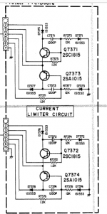
I have not followed all details of this tread, but I had the same symptoms on an LV-103 after I had to replace MOSFETs.
Turned out to be damaged (shorted) transistors on the Current Limiter board of one channel. Disconnected the board and now turns on. I did not have any replacement transistors of correct type for repairing, so the amp see little use.
I am running a 2SK1056/2SJ160 on the output I believe I should fix the current limiter to avoid new damage since the temperature drift of these transistors are different from the originals.
Can I use generic transistor types in this circuit or do you believe type and Beta of Q7372/Q7374 to be critical?
Attachments
had you tried replacing the IC? Mine is acting weird before when i replaced it works as expected. on my LV103, it's the tube heating issue, so it really affected the time on of relay. my 6cg7 has slow warm up than the other so i replaced it with New.
I do get - 0.75 V at Q8301 collector but I now measure + 0.70 at pin 1.
However I get + 61 V at B and E, instead of 52 V.
The 47k measures 40 k by the way, but the 180 k is spot-on.
I very much doubt the new chip will solve that.
Quite a few posts since yesterday 🙂
This is where using the scope comes into its own. You need to look at those voltages with a scope. Q8301 should be off and so the voltage at either end of R8309 should be the same.
47k measures 40k. Either the value is different to the manual or it has gone low which can happen. It needs checking.
I was thinking like Marcel on the mains voltage and tolerances but then thought that if the pos rail was to high then the negative rail (on the 1uF) would also increase and maintain the ratio between the two.
Good morning!
I do stock new 47k resistors. Let’s try that first!
The new chip should be here tomorrow by the way.
I do stock new 47k resistors. Let’s try that first!
The new chip should be here tomorrow by the way.
Last edited:
Mooly, I don't think the highish voltage is the root cause either, but it would still be interesting to know why the 52 V has grown to 61 V: maybe this points at some other problem, maybe there is a simple explanation for it.
Indeed 🙂
It will be very interesting to see what the outcome of the new chip (and the 40/47k) reveal.
It will be very interesting to see what the outcome of the new chip (and the 40/47k) reveal.
As I suspected, renewing the 47k doesn't have any effect: + 0.7 V on pin 1, 100 mV on pin 8. I insist that everything else is on spec.
As for what's going on around Q8301, I don't have a clue either.
I can't find any bad components in fact! The caps I needlessly replaced all had correct values and low ESR.
The scope does not show anything odd by the way - I should've told you that before.
Main supply: +/- 62 V, no ripple.
Tell me how I can get that - (minus) 0.75 V on pin one please.😀
Last edited:
It will also be very interesting for me too to see if replacing the chip makes any difference as that's what I suggested many posts back .
I can only be right -----or wrong-- and at the small price of the chip its no"big deal ".
I can only be right -----or wrong-- and at the small price of the chip its no"big deal ".
Hi Duncan,
Sure. My intent was to learn how the thing actually works - when it does, as well as fixing that amp. A definite keeper. This thing sounds gorgeous.
Sure. My intent was to learn how the thing actually works - when it does, as well as fixing that amp. A definite keeper. This thing sounds gorgeous.
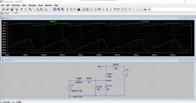
This is the setup as I see it. If you have 62 volt rails then that must equal the peak AC voltage... set here at 62 volt.
The voltage on pin 1 depends on three things which are the voltage on pin 9 is, by how much pin 1 loads the circuits and also what Q8301 is doing.
You have measured the voltage on pin 9 as being about 2.98 volts. (I set it to 2 volts... won't make much difference)
Q8301 should be off. We can emulate that by lifting the 47k to its collector so it has no influence.
That leaves loading of the chip as the unknown variable. The application note shows pin 1 to be a base emitter junction and so that is what the second image shows.
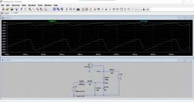
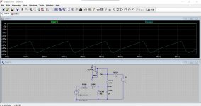
Could there be an internal protection diode on pin 1 to prevent reverse biasing to any large degree... that's quite likely in an IC because any such situation if it occurred can turn on 'parasitic' parts and cause total non functionality. The chip might even latch up.
That's the third and fourth image image.
The voltage on pin 1 depends on three things which are the voltage on pin 9 is, by how much pin 1 loads the circuits and also what Q8301 is doing.
You have measured the voltage on pin 9 as being about 2.98 volts. (I set it to 2 volts... won't make much difference)
Q8301 should be off. We can emulate that by lifting the 47k to its collector so it has no influence.
That leaves loading of the chip as the unknown variable. The application note shows pin 1 to be a base emitter junction and so that is what the second image shows.
Could there be an internal protection diode on pin 1 to prevent reverse biasing to any large degree... that's quite likely in an IC because any such situation if it occurred can turn on 'parasitic' parts and cause total non functionality. The chip might even latch up.
That's the third and fourth image image.
Attachments

In an old-fashioned bipolar process, the parasitic diodes are from the NPN collectors to substrate and from the PNP bases to substrate, so you can pull an NPN base negative without turning on unintended junctions. There could nonetheless be a diode to prevent emitter-base avalanching, though - voltages below -5 V or so could otherwise blow up the base-emitter junction.
Your simulations all show that the NPN turns off as it is supposed to.
Your simulations all show that the NPN turns off as it is supposed to.
Would it make sense to repeat the R8309 lifting experiment, so to check what happens with everything else connected normally, but one side of R8309 disconnected? At least you have a circuit that should match Mooly's simulations then.
- Home
- Amplifiers
- Solid State
- Luxman LV105 protection IC woes