If pin 8 needs to be close to 2V, it means Q8304 should have its collector and emitter open or base to emitter at 0V or fully OFF and Q8305 turned ON or fully saturated. The 2SC1815 are high gain transistors but not exactly low VCEsat, they go down to 0.1V if driven hard.
Q8304 and Q8305 are basically logic inverters with open collector. The resistor on their collectors are logic pullups tied to an appropriate DC voltage. Measure the base voltages of these transistors and confirm if the collector to emitter/ground voltages follow the input, 0.6V on the base equals 0.1V at the collector to emitter. If the base voltage is 0V-ish then the collector voltage will be about the same potential as the other end of the collector’s pullup resistor.
Q8304 and Q8305 are basically logic inverters with open collector. The resistor on their collectors are logic pullups tied to an appropriate DC voltage. Measure the base voltages of these transistors and confirm if the collector to emitter/ground voltages follow the input, 0.6V on the base equals 0.1V at the collector to emitter. If the base voltage is 0V-ish then the collector voltage will be about the same potential as the other end of the collector’s pullup resistor.
Hi,
This makes sense.
The way I see it, Q8304 is just a switch that will kind of short pin 8 to ground (via the 1k resistor) and therefore trigger the internal muting circuit, thus switching the relay off.
However, this doesn't explain excessive current draw on pin 8.
This switch will mute the amp if there's a defective valve or if the heat sensor detects excessive heat.
With the 1k lifted, supposing there is a fault - there isn't - there should be about 1.3 V at pin 8 with the 100 k resistor in place.
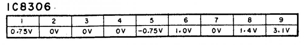
I don’t see you giving the voltage readings from all 9 pins, if this was done on post #6 then you are not very clear about it. Pins 1,2,3 & 7 will override pin 8 under normal condition. Connecting a low resistance between pin 8 & 9 defeats this so you are not really addressing the root cause but adding another variable by forcing higher current on pin 8 that normally requires several uAs only. I don’t condone this practice without fully understanding the consequences. This method is not troubleshooting but adding more problems.
You mentioned 2.5mA with the 100k, that’s 250V across 100k.
You mentioned 2.5mA with the 100k, that’s 250V across 100k.
Last edited:
Sorry, 2.5 mA was across a 2.2 Ω resistor!
I just wanted to know whether the delay at switch-on worked, and it does (28 seconds). Nothing more.
Yes, I did check all pins, including AC at pin 1 - only 8 is not within specs. That's why I tried that.
Through the 100 k I get absolutely no voltage reading at all.
I just wanted to know whether the delay at switch-on worked, and it does (28 seconds). Nothing more.
Yes, I did check all pins, including AC at pin 1 - only 8 is not within specs. That's why I tried that.
Through the 100 k I get absolutely no voltage reading at all.
Attachments
Last edited:
OK 🙂 I guess you really do have to try that chip now... it's never the chip... but very occasionally it is 😉
Good luck for when it arrives.
Good luck for when it arrives.
Just one more thing because I haven't studied it all in detail... all the voltages you measure... it might be worth using a scope to confirm they are all clean voltages and not some 'average' a DVM is interpreting as being correct.
It hadn't crossed my mind, except for what's on pin 1 - a nice sawtooth signal!
My DMM had instant and average readings, that said.
My DMM had instant and average readings, that said.
OK. That could be normal but worth a look at C1316 which is a 1uF. That would be a another typical cap in a failure prone position although the 1k feeding it will greatly ease its life.
Worth substituting.
(I always used to use a scope for fault finding back in the day as it reveals all kinds of horrors on what you think are clean and correct rails and voltages)
Worth substituting.
(I always used to use a scope for fault finding back in the day as it reveals all kinds of horrors on what you think are clean and correct rails and voltages)
Already done.
Just a thing that puzzles me. What does Q8310 do? I get wrong values here: + 62V (E-B) and +0.7 V (C). I just tried another Zener to test but no difference.
Just a thing that puzzles me. What does Q8310 do? I get wrong values here: + 62V (E-B) and +0.7 V (C). I just tried another Zener to test but no difference.
You mean Q8301? Can't just see a Q8310
If Q8301 then that would have positive supply less the Zener voltage on the emitter but Zeners are so leaky you would read supply voltage unless the transistor was conducting. The base would read similar voltage to the emitter.
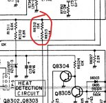
It looks to be overcurrent protection, turned on when either Q7323 or7324 turn on. Q8301 should normally always be off. You could lift R8309 as a test.
If Q8301 then that would have positive supply less the Zener voltage on the emitter but Zeners are so leaky you would read supply voltage unless the transistor was conducting. The base would read similar voltage to the emitter.
It looks to be overcurrent protection, turned on when either Q7323 or7324 turn on. Q8301 should normally always be off. You could lift R8309 as a test.
The delay looks to be set by the time constant on pin 8 i.e the 100k and 47uF but that would not give 30 seconds, more like about 4 seconds.
So what about the other time constant acting on Q8305 which 'overides' the 100k and 47uF.
Just looking quickly at the circuit Q8304 is turned on immediately via R8324 and that will keep the 47uF discharged. No relay on.
C8305 now slowly charges via the 560k and when it can turn on Q8305 this pulls the base of Q8304 down thus allowing the original 100k/47uF constant to kick in.
Just looking quickly at the circuit Q8304 is turned on immediately via R8324 and that will keep the 47uF discharged. No relay on.
C8305 now slowly charges via the 560k and when it can turn on Q8305 this pulls the base of Q8304 down thus allowing the original 100k/47uF constant to kick in.
Maybe the 30 s delay is set by R8326 and C8305. R8326 * C8305 = 263.2 seconds nominal, but C8305 only needs to get charged up to 0.7 V or so to turn on Q8305, turn off Q8304 and release pin 8 of the TA7317P.
Edit: I see Mooly came to the same hypothesis as I was writing this post.
Edit: I see Mooly came to the same hypothesis as I was writing this post.
- Home
- Amplifiers
- Solid State
- Luxman LV105 protection IC woes