Hello, I'm currently trying to repair a Luxman L-3 that I bought at a thrift store to make it mine and enjoy! For now I've read all the previous posts made on this forum and though I found the issue when I changed a resistor that was problematic for someone else (mine also was bad). Replaced the resistor with one that was good (Amazon) and tried to turn it back on... ohoh the dim light tester stays on.
That was my initial try at repairing it, since then, I tried to find the short, but I can't seem to find anything promising. I used a thermal camera to identify hot spots on the power board and found to spots, one around the D403 and D404 diodes and the Q408a area. Since then I pulled all the components to test them outside the circuit, but they all seem to be good from my understanding.
I'm kinda lost and don't know what I could check before starting to resolder all the components back on the board, do you guys have any wisdom to share that could help me with my project! Thanks. There seems to be a good amount of info on this site about the amplifier so if you want something specific let me know and I'll share it with you (schematic, components list, voltage drop of the components I pulled, etc.).
Attachments
What "high" voltage did you see at the spkr terminals.
Near rails voltage might point to failed output or driver or... transistors.
One or both channels affected
Once repaired, consider fitting one of those protection kits available on the bay or the diystore or...
Near rails voltage might point to failed output or driver or... transistors.
One or both channels affected
Once repaired, consider fitting one of those protection kits available on the bay or the diystore or...
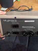
The voltage was ±37 V at the terminals for both channels, after changing the resistor (R406 which was reading 0.9 M ohm) the voltage was at ±10 V but with the dim bulb lighting up (60W bulb).
With R406 stressed it is suggested to check downstream components, ie, zener DZ401a, check cathode voltage, nominal +19Vdc?R406 which was reading 0.9 M ohm
I didn't test the voltage initially at the zener diode and now I got a bunch of components off the board, could I remove the zener and test it with a multimeter?
Yes you could use the diode test function on your MM, test both orientations, expect 0.6V and OL, however the best test is under load/in circuit by measuring the voltage at the node common to DZ-401a/R403a/R406a, ie, measure Vdc at either of these components will suffice since they are all connected.could I remove the zener and test it with a multimeter?
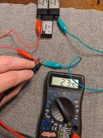
Got too much components off the board so I tested it them outside the board with this setup! Tried to test it in diode mode first, got 0.789 V and OL the other way around. A little bit higher then what you told me so decided to test load it.
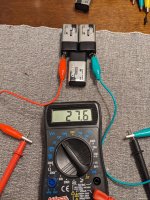
Got this setup going, 3x 9V batteries in series with 1.5k ohm resistor in series to get close to the 19.25 V it's rated for. Everything seemed to be fine, reading about the same voltage drop at the diode. Then tried with something a bit more powerful, 27.6 V (no resistors) and got a reading of 23.2 V, shouldn't it be staying around 19-20 V max? Also it burned some of my plastic leads so I'm guessing it's getting hot. Could that mean that the diode failed?
If so what can I replace it with? Got any alternative you know? A quick search gave me this on digikey ; https://www.digikey.ca/en/products/detail/nexperia-usa-inc/NZX20A-133/2119733
Could that work?
Attachments
Did not show short or open so looks ok, sure the Vf might be high, should consult datasheet but thinking it's no big dealdiode mode first, got 0.789 V and OL
Looks good3x 9V batteries in series with 1.5k ohm resistor in series to get close to the 19.25 V it's rated for.
Diode looks ok, you need to be careful not to exceed the power rating, probably should be looking elsewhere, other candidate would be Q401, Q402Then tried with something a bit more powerful, 27.6 V (no resistors) and got a reading of 23.2 V, shouldn't it be staying around 19-20 V max? Also it burned some of my plastic leads so I'm guessing it's getting hot. Could that mean that the diode failed?
DBT is somewhat bright, schematic shows fuses on the power amp +/- rails, have you tried pulling the +/- fuses from one channel, does DBT normalize, reinstall fuses and pull fuses from other channel. Trying to work out if there is high current flow and if that flow is through R406 and then possibly through R403, Q1,2.... Any signs of stress on R403?
probably should be looking elsewhere, other candidate would be Q401, Q402
I did take some measurements before changing the R406 resistor at all the transformers here was the voltage ;
Q401a/b
E = 0.65/0.65
B = 25k (0v)/25k (0v)
c = -36.5/-36.6
Q402a/b
E = 0.65/0.65
B = 11.5/10.99
C = -37.1/-37.2
Q403a/b
E =-37.3/-37.28
B =-36.75/-36.7
C =34.89/33.93
Q404a/b
E =n/a
B =n/a
C =n/a
Q405a/b
E =35.15/34.47
B =35.55/35
C =37.4/37.43
Q406a/b
E =35/34.4
B =34.85/33.94
C =-34.56/-34.5
Q407a/b
E =34.37/33.1
B =34.3/33.17
C =34.3/34.3
Q408a/b
E =34.2/33
B =33.6/33
C =-34.16/-34.16
Voltage on the zener:
DZ401b= 0.644v / open other
DZ401a= 0.644v / open other
DBT is somewhat bright
Not too sure what this means...
Any signs of stress on R403?
I also took all the resistor measurements before changing R406 and the only one that was reading off was;
R406 @ 0.9M ohm,
R425 was reading @ 171k ohm in circuit but 330k ohm outside
R426 was reading @ 0.4 ohm in circuit but 47 ohm outside.
Nothing seemed off in my opinion, all the other resistors are in spec in circuit!
My take on your problem is,
Looked downstream R406 for possible root cause of R406, DZ401 identified as likely candidate, it tested ok. Other downstream candidates would be in the area of Q401,2
Maybe I've misinterpreted the DBT being abnormally bright, you are using a low wattage bulb(60W) Did you try a 100W item. Normal behaviour is there should be a brief flash at power on then the bulb should be off or maybe very dimly lit for a 60W bulb. Certainly using a dbt will have an affect on the rail voltages. A bright dbt means the amp is drawing abnormally high current, eg, if DZ401 failed short there would be a low impedance path to GND.
You need to make a call on whether the dbt is somewhat bright, and if not, whether you can power up without dbt then recheck rails voltages.
If the dbt is bright then you could try to localise the area by disconnecting various stages, eg, removing power amp fuses as in post #8, at the moment we think it's with the power amp because of the failed R406
- R406 stressed/open due to high current
- power amp rails voltage sagging somewhat
- DBT abnormally bright
Looked downstream R406 for possible root cause of R406, DZ401 identified as likely candidate, it tested ok. Other downstream candidates would be in the area of Q401,2
Maybe I've misinterpreted the DBT being abnormally bright, you are using a low wattage bulb(60W) Did you try a 100W item. Normal behaviour is there should be a brief flash at power on then the bulb should be off or maybe very dimly lit for a 60W bulb. Certainly using a dbt will have an affect on the rail voltages. A bright dbt means the amp is drawing abnormally high current, eg, if DZ401 failed short there would be a low impedance path to GND.
You need to make a call on whether the dbt is somewhat bright, and if not, whether you can power up without dbt then recheck rails voltages.
If the dbt is bright then you could try to localise the area by disconnecting various stages, eg, removing power amp fuses as in post #8, at the moment we think it's with the power amp because of the failed R406
I did take some measurements before changing the R406 resistor at all the transformers here was the voltage ;
Q401a/b
E = 0.65/0.65
B = 25k (0v)/25k (0v)
c = -36.5/-36.6
Q402a/b
E = 0.65/0.65
B = 11.5/10.99
C = -37.1/-37.2
Q403a/b
E =-37.3/-37.28
B =-36.75/-36.7
C =34.89/33.93
Q404a/b
E =n/a
B =n/a
C =n/a
Q405a/b
E =35.15/34.47
B =35.55/35
C =37.4/37.43
Q406a/b
E =35/34.4
B =34.85/33.94
C =-34.56/-34.5
Q407a/b
E =34.37/33.1
B =34.3/33.17
C =34.3/34.3
Q408a/b
E =34.2/33
B =33.6/33
C =-34.16/-34.16
Voltage on the zener:
DZ401b= 0.644v / open other
DZ401a= 0.644v / open other
Here's my take on how the PA should be behaving, given their current misbehavior. Both channels seem to have similar issues.
Starting with a given that PA outputs are stuck at +34V: Base of Q402 is +11.5V, so input diff pair should be directing all tail current through Q401.
Vbe at Q403a is 0.55V, which might be a bit low. Confirm about +19V at cathode of DZ-401a and viable/correct VR401a (4.7K) and R403a (6.8K) resistors and that associated traces are intact.
In any case, bias feedback should be forcing Q403a into conduction, but this doesn't seem to be happening. Perhaps Q403a has failed. If you haven't found anything amiss in the input stages, as a test, tack a 15k resistor from Q403a base to ground. This should be enough base current to force Q403a into saturation and the output stages into the negative rail. (Be certain to test with no load connected to PA.)
Let us know what you observe. Good luck.
- Home
- Amplifiers
- Solid State
- Luxman L-3 project - High voltage at speaker terminals