The HT will be hybrid, the filaments will be DC driven.
Meantime, the Fostex FE127 single drives have arived. I want to use this amp with the Fostex speakers. Well, it is kind of "late" question, but is the BV sufficient for the Fostex speakers?
trif.
😉
Meantime, the Fostex FE127 single drives have arived. I want to use this amp with the Fostex speakers. Well, it is kind of "late" question, but is the BV sufficient for the Fostex speakers?
trif.
😉
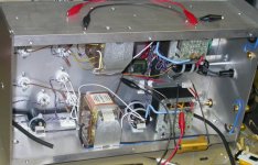
I have noticed that the screews used to keep together the choke plates is not fully tighted.
Is this normal for a choke?
trif.
Is this normal for a choke?
trif.
trifidmaster said:I have noticed that the screews used to keep together the choke plates is not fully tighted.
Is this normal for a choke?
trif.
You may tighten them. Also, if you don't intend to rewind your choke one day you may coate it by epoxy.
trifidmaster said:How much time is needed for "burn in" the tubes?
trif.
It depends on a post-hypnotic suggestion.
trifidmaster said:Uhhh, now I am lost...can you elaborate more?
Break-in is a well known effect in the Hi-End business.
Trance state induction is needed, it means good rapport and tight feedback between a person who sells and a person who buys, in such case suggestions works well and break-in happens exactly as predicted, with the greatest satisfaction. Tubes, cables, amplifiers, and even whole systems may be breaked-in to the best satisfaction of the owner. Sometimes, fellow audiofiles and articles interfere, so break-in happens at a different time, and while listening to a different music.
Sorry if I misunderstood your question.
trifidmaster said:The electronics is done by my colleague.
The amp is evolving and I am learning a lot...from him.
If I see well, you have only one ground wire going to each filter capacitors. I'll suggest you to wire them step by step, as shown on the schematics, from transformer and rectifier to the cap, from the cap to the chocke to another cap together with the ground wire, and so on. Ground wire is actually very loong in terms of big currents and small signals, so ground near the rectifier and/or power transformer is completely different ground wire than near the input socket!
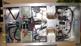
The grond wire is 2.5 mm2. We will post another picture where the grounding is more clearly visible. OK?
Thomas and trif.
Thomas and trif.
Yesterday Thomas could finish the building of the amp, and
we turned ON the amp - BIG MOMENT.
Note: No GLOBAL feedback is implemented yet.
Both channels worked! 😀 😀
Thomas checked the voltages, and all values were as planned.
And we started to listen to the amp with several CDs,
and at the certain moment we have observed CLIPPING - the input stage was CLIPPING.
Paralel to the cathode rezistor one mkp and one elko cap were mounted.
We have measured with the scope the signal - coming from the CD player (Philips CDR570) - and it had 2.8 V high peaks
Note: we do not know if this is normal for a CD player.
The plate current of the input stage at this point was 14.5 mA and the grid voltage was slightly negative but surely no enough for such a high input signal.
So, we have changed the cathode and plate rezistors, and the plate current became 4.5 mA, and the grid voltgae became -2.4 V. We have removed the cathode capacitors/per channel.
Certainly the clippind was reduced - but still audible with some CDs.
BUT the sound became completley unacceptable: it was more tight, no spaciness, kind of dry and woody sound. Installing back the cathode capacitorss the sond became more acceptabe, but still not good.
Finally we put back the original rezistors for the plate and the cathode.
I have learned: more inputstage anode current has a nicer sound, and the cathode capacitors have also nice effect on the sound.
Lower plate current has a tighter sound. The input stage has VERY BIG effect on the sound.
Any suggestion(s)???
Thoams and trif.
At this moment I like to hear from you gens what do you think about my observations.
Actually, I am used to listen to my studio monitors - Dynaudio 2.1 system what just sound very good for many different type of music. The frequency response in my room is +-3dB. So, I have something good to compare my tube amp.
But I am not that stage yet, since the sound what comes out from my PP tube amp is far from what I like to have.
Why is the higher plate current better sounding compared to the lower one? (14.5 mA compared to 4.5 mA)?
Why the caps installed paralell on the input stage cathode rezistor sound better?
We have another issue - to be solved:
As I wrote earlier, the rectifier is hybrid and made by an excellent 5U4G. Very nicely looking tube.
Turning on the amp, this tube kicks in faster (in about 5-8 secs.) compared to the EL84s.
Without any protection the voltage on the rectifier cap could evenutally go high (over or very cloose to the voltage rating of the rectifier cap=450V), therefore we plane to implement a delay for the heater of the 5u4G. Sure, I could go for another tube diode (what kicks in slower), but for the time beeing I like very much the look of this beauty=5U4G.
For the moment we have put a power rezistor between the HV and ground so that we have already a consumption of the HV before the EL84 s kicks in and the HV never goes too high.
trif.
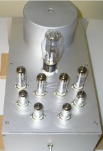
Looks nice!
But if you like the 2'nd harmonic it means you like lower resistance load of a triode, it not necessary means higher current.
But if you like the 2'nd harmonic it means you like lower resistance load of a triode, it not necessary means higher current.
Wavebourn,
How do you know that I like 2nd harmonics?
Please tell me more, I am now very curious.
trif.
How do you know that I like 2nd harmonics?
Please tell me more, I am now very curious.
trif.
trifidmaster said:Wavebourn,
How do you know that I like 2nd harmonics?
Please tell me more, I am now very curious.
trif.
Correlation between schematics, oscillograms, and sounds in imagination. No miracles, just an experience. 😎
Wavebourn said:Looks nice!
But if you like the 2'nd harmonic it means you like lower resistance load of a triode, it not necessary means higher current.
Are you sure? Is it not the opposite way?
Wavebourn said:
It does not depend on the schematic which is classical in this particular case. With different output transformers you'll get very different results.
However, I would decrease impedance of the feedback loop 10 times splitting cathode resistor by 1.2K bypassed by a capacitor and 100 Ohm in series, 27K resistor in the feedback would be reduced to 2.4K. Correspondingly, the capacitance in parallel with this resistor will be increased until the amp get stable on highs. Or, you may leave the cathode resistor as is, connect to the cathode one 100 Ohm resistor with 1000 microFarad capacitor in series, negative leg of the cap is grounded, and feedback will go to the point of interconnection of the 100 Ohm resistor and the capacitor.
It will decrease a local feedback in the 1'st stage increasing gain; the overall feedback will bne deeper, and non-lineariries in the feedback loop will be reduced many times.
Wavebourn,
If you read my very 1st post in this thread, you can see that I am using the 6922 tube. This tube typically uses 80-100 Ohm cathode resistor (I have 100 Ohm cathode resistor). Now, how can I split this 100 Ohm into 1.2K and 100 Ohm in series?
trif.
- Status
- Not open for further replies.
- Home
- Amplifiers
- Tubes / Valves
- Lundahl+EL84 PP+concertina+input stage