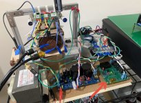
Well, I am playing the amp at 6.0A bias current and maintaining 28.1vdc at the amp supply now with both secondaries of the the 400VA trafo being employed. (This says that if running 3A bias current, a single 400VA trafo should be enough for a dual mono stereo setup). I decreased the resistance and increased the power dissipation of the CRC resistor by using 4x 0.33ohm 3W Vishay in parallel. With two in parallel the resistor was hitting 190C, now running at 104C. Music sounds good! Temp of LD1014D body is 54C and air blowing out of CPU cooler for the three MOSFETs is 50C - fan speed kicked up a notch with the auto temp feedback speed of the PWM controller doing its thung.'
The amp is still absolutely silent with no music playing. Quiet as in you cannot tell it is turned on with ear pressed to speaker cone. The DIY Sony VFET amp is also like this but uses a SMPS whereas here this is a linear supply.
Video from my phone of test track:
LuFo amp running at 6.0A bias current and 28.1v. Driving 10F/RS225 TL speakers. - YouTube
Do the MOTs get hot?
No. Barely warm - 6A^2 x 0.5R is 18w for a 10lb chunk of steel and copper is nothing.
Last edited:
Interesting. 6A ^2 * 0.5 ohms = 18 watts. I would expect the copper winding to get warm and eventually transfer that to the core. Can you aim your IR thermometer at the copper primary winding?
It would probably take at least 30min to reach full temp. I’ll take a reading when I run it again later.
It would probably take at least 30min to reach full temp. I’ll take a reading when I run it again later.
Copy that. I am behind you many days. Hope to have a start by the end of the week.
It would probably take at least 30min to reach full temp. I’ll take a reading when I run it again later.
After 1hr at 6A bias current but no music playing, MOT primary was 42C and steel core 30C.
After 30 min of full power 40w sine wave testing, MOT primary was 70C and steel core was 55C.
Sine wave testing definitely heats the MOT vs DC only.
will be nice with non allien music.... 😛Video from my phone of test track:
LuFo amp running at 6.0A bias current and 28.1v. Driving 10F/RS225 TL speakers. - YouTube
After 1hr at 6A bias current but no music playing, MOT primary was 42C and steel core 30C.
After 30 min of full power 40w sine wave testing, MOT primary was 70C and steel core was 55C.
Sine wave testing definitely heats the MOT vs DC only.
Nice measurements. Thank you for sharing.
I added a SSR soft start circuit to the LuFo today. Upon power up, the trafo is fed AC mains through three NTCs in series (about 24ohms) for 2 seconds, then a pair of back to back low RDson MOSFETs controlled by an optoisolator is then switched on to bypass the NTCs.
It’s much nicer than burning off all the current as heat through a full time NTC as a soft start.

I connected my 10F/RS225 TLs in parallel to the mono speaker outs (4ohms nominal combined) to get a better sense of the sound from two speakers. It’s driving 4ohms no problem.
It’s much nicer than burning off all the current as heat through a full time NTC as a soft start.
I connected my 10F/RS225 TLs in parallel to the mono speaker outs (4ohms nominal combined) to get a better sense of the sound from two speakers. It’s driving 4ohms no problem.
Attachments
My order for some OPA454’s came in. We are going to design a custom M2X format daughterboard that will go onto the main amp PCB to provide high swinging output - up to 50mA and +/-50v. The 454 has 0.0008% THD spec so should be fine for the 0.01% nominal THD of the LuFo.

Please let us know if your ACP+ or M2x/Yarra is ready for this application or it is necessary to modify it 🙂
The Yarra with Melbourne daughterboard and the proper +/-30v transformer PSU can drive this amp without any problem.
Sorry, I intended your ACP+ daughterboard For M2x
Please let us know if your ACP+ or M2x/Yarra is ready for this application or it is necessary to modify it 🙂
- Home
- Amplifiers
- Pass Labs
- LuFo Amp - 39w SE Class A from 28v Rail