An LCR meter is also good. DATS works well. My Fluke 101 and 115 cannot measure anything under 2ohms accurately.
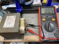
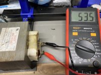
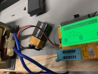
dBel beat me to the punch! I also just took a chance on one of the 903 series. This one being the AMR. With my LCR meter I’m getting 0.5 DCR and 53.5mH. Also took a reading with the old parts tester. DCR also 0.5 but maybe not the best at measuring inductance.
Attachments
Last edited:
Jwjarch,
I would not be surprised at 100mH as the core is almost twice as thick. Thanks for confirming that the 903AMR is also viable.
I would not be surprised at 100mH as the core is almost twice as thick. Thanks for confirming that the 903AMR is also viable.
It is fairly easy to build a 1.0 Amp current source, then use that to derive the DCR of chokes and confirm other low value resistances.
Europeans: check SU90b c-cores which are also rated for some 600 watts.
When interested I have a friend willing to do some support.
Hi Daanve, is there a webshop for these c-cores? Google did not come up with anything usefull.
https://www.google.com/url?sa=t&rct=j&q=&esrc=s&source=web&cd=&ved=2ahUKEwjFkPSdlZnxAhUPHewKHbFrAaIQFjACegQIBBAE&url=https%3A%2F%2Fwww.semic.cz%2F!KATEGORIE%2F6K%2FCatalogue%2520Silicon%2520steel%2520cores.pdf&usg=AOvVaw2beLQIUuSzGLeh9_BzvOug
https://www.google.com/url?sa=t&rct..._06_2018.pdf&usg=AOvVaw1M9_t8r0k2n5WltkA0YO4G
https://www.google.com/url?sa=t&rct..._06_2018.pdf&usg=AOvVaw1M9_t8r0k2n5WltkA0YO4G
Last edited:
Nope 😀 it's Fabbrica Induttanze Alimentatori e Trasformatori:
Progettazione e Produzione Componenti Elettromagnetici Roma – F.I.A.T Srl
Speriamo che in Italia costi meno...
Grazie per aver trovato l azienda e chiesto un preventivo
Forse se facciamo un GB i prezzi saranno buoni...
Hi Adason,
Thanks for pointing that out. Yes, does look similar but the coupled transformer load provides several key benefits: increased efficiency (50% thermal) since it’s a reactive load, inductive coupling feedback between the two legs makes it technically a SuSy topology so that the distortion is reduced, and the peak power is now 4x what is normally possible with the same rail voltage. 100w from 28vdc rail that makes 80Vpp is quite a feat if you think about it.
I fully agree...considering how tiny those critters are.
Inductor DCR Measurement
How do you check the resistance of an inductor? You can't just use your multimeter on ohms setting.
Suppose you need to measure a device like an inductor with DC resistance in the milliohm range. We had a production quality issue and needed to evaluate some inductors. The target resistance of the part was between 63 and 70 milliohms. Try to measure it with your Fluke 87V and you'll read something in the 0.5 ohm range. So how do you accurately measure it without an expensive micro-ohm measuring instrument? This is how we did it:
Make a "test fixture" from copper tape and a half business card. Add Kelvin sense leads. Solder the inductor on the fixture. Connect the Fluke 87V to the sense leads in voltage measurement mode and connect the power supply to the (copper tape) power leads with current limit set at 1 amp. The reading in millivolts drop on the sense leads is equal to milliohms of DC resistance in the part. Done.
The actual way to measure an Inductor's DCR value is by using a Kelvin sensing path across the leads and applying current across the Inductor. As the DCR of Inductor is the DC resistance of the copper wire, it will produce a voltage across the Inductor's terminal based on the Ohms law, V = I x R.
Attachments

On my working LuFo I measure 3A independently from the CRC resistor - and the voltage across the inductor is 1.5v. This gives me an in-use, at operating current DCR of 0.5ohm which matches what the LCR meter gave when I measured the inductor at the mA used by the LCR meter.
good, might be coincidence, just like when you measure speaker resistance with multimeter, you get some number anyway, which is off due to inductance, but sometimes you get lucky

A bench top regulated and current limited supply is also handy to use as a source for testing an inductor. Here is my Instek GPC-3020 that I used to test the JFETs.
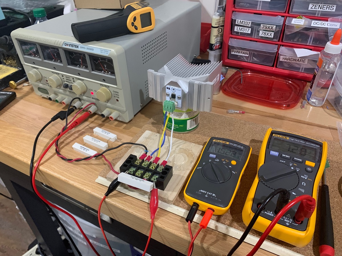
These massive linear supplies can be found on eBay at great prices.
These massive linear supplies can be found on eBay at great prices.
X,
Agreed! I use a Siglent power supply which is very handy to bench test these Class A amp boards prior to the final install.
Best,
Anand.
Agreed! I use a Siglent power supply which is very handy to bench test these Class A amp boards prior to the final install.
Best,
Anand.
Last edited:
I generally use a signle IXYS and a CPU cooler and fan as the heat flux of 75w from a single part is probably more than a passive heatsink can spread out well spatially. Hence the choice to use several lower power rated, less expensive MOSFETs to permit spreading the thermal load over a wider area to keep the part well within it safe operating area. The three TO-247 MOSFETs spread over a 300mm deep heatsink in DIYA UMS format allows for more people to be able to build it as many are not comfortable or will even consider non-passive heatsinsks.
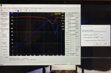
Ok, ok. So I don’t have the time to use my brain power to figure out how to build a test bed. But I did use my brain power to remember I have a DATS V2 laying around my shop! 😀
Here are the results. Almost dead on 0.6 DCR and 75mH for the 903AMR.
Here are the results. Almost dead on 0.6 DCR and 75mH for the 903AMR.
Attachments
- Home
- Amplifiers
- Pass Labs
- LuFo Amp - 39w SE Class A from 28v Rail