While exploring the idea of getting an LL1540 and taking a second then a third look at the LuDEF schematic, the M2x schematic, the SissySIT schematic it became clear that I had no clue how the amp works. 🙄 
 In my speed-reading of the schematic I missed the differences with the Sissy and the M2. I realized Lundhal I was looking at was 600/15k while the LuDEF seems to use a 600/600.
Can someone please explain to me how the amp actually works? Or point me to a relevant link? Where is the voltage gain coming from on the LuDEF and how to go about using the LL1540.
In my speed-reading of the schematic I missed the differences with the Sissy and the M2. I realized Lundhal I was looking at was 600/15k while the LuDEF seems to use a 600/600. Can someone please explain to me how the amp actually works? Or point me to a relevant link? Where is the voltage gain coming from on the LuDEF and how to go about using the LL1540.
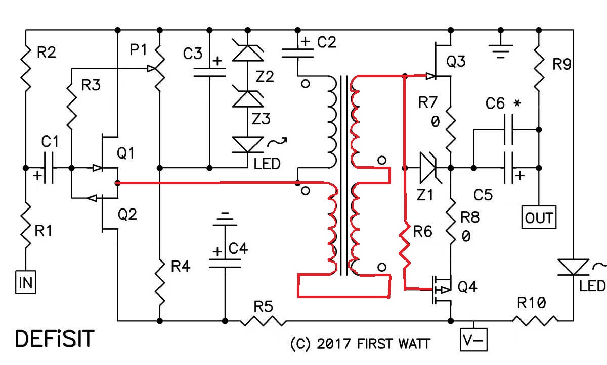
post #58 Most Greedy Boy, of them all... or (there is no) DEFiSIT of Papa's Koans
principle is same
ignore first gen(s) of SissySIT and B. M25 - if you want to avoid confusion regarding Edcor xformers (is it 600:15K or 600:600)
in any case , disregarding of minor gain differences between these two xformers , principle is the same
principle is same
ignore first gen(s) of SissySIT and B. M25 - if you want to avoid confusion regarding Edcor xformers (is it 600:15K or 600:600)
in any case , disregarding of minor gain differences between these two xformers , principle is the same
ZM,
It's hard without the boards in hand. I have some idea and I will try to figure it out once I get them. I PM'd you earlier.
this could be helpful
Attachments
well, I can't explain better than posting schematic, which I did in post #1

if you can ask some more specific question, if you don't understand some part of amp function.... I would be happy to explain, as much I'm able .....
if you can ask some more specific question, if you don't understand some part of amp function.... I would be happy to explain, as much I'm able .....
ZM, how did you avoid the output cap in the LuDEF?
Original Pass DEF uses unipolar power supply. Speaker ouput is halfway between power rail and ground and needs a cap. ZM's LuDEF uses bipolar power supplies and speaker output is halfway between the power rails which is zero volts referenced to ground and does not need a cap.
The LuDEF also has a trimmer pot to adjust the output DC offset. Apparently the temperature and rail voltage sensitivity is not a serious problem and the optocoupler circuit for bias current control is enough.
Thanks woofertester and lhquam! I did see the two rails and the optocoupler biasing and P103 for setting DC offset. I just thought it wasn't possible (or not easily possible) to have stable DC offset with the depletion-enhancement setup, which is why the output cap is there as an easy way to get out of doing a lot of extra work. Guess Papa was going for simplicity and doesn't mind the output cap.
I still don't fully understand the details of how output bias is pulled close to zero with temperature drift and rail changes (as lhquam mentioned). But don't tell me--I want to figure it out.
I still don't fully understand the details of how output bias is pulled close to zero with temperature drift and rail changes (as lhquam mentioned). But don't tell me--I want to figure it out.
you have some interesting reading, starting from post #32
print schm from post #1, place it aside and read ...... you'll get it
print schm from post #1, place it aside and read ...... you'll get it
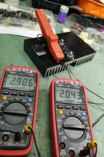
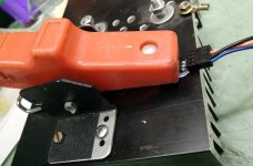
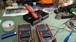
I forgot to post these
after all these years I finally made (semi)automatic thumb
one half of car cable clamp, bolted to sink, metal flange got piece of wire PVC isolation around, to serve as pressure point cushion
now, they're all confessing, without my thumb being sore

after all these years I finally made (semi)automatic thumb
one half of car cable clamp, bolted to sink, metal flange got piece of wire PVC isolation around, to serve as pressure point cushion
now, they're all confessing, without my thumb being sore
Attachments

Alrighty, mighty ZM, I did my best to study the circuit and your posts on page 4 of this thread. It was really helpful to understand how things are working, starting with the M2. Now, I am by no means a circuit expert, so please help me understand.
1. Starting with the M2 circuit. Purpose of optocoupler is to keep current through OS constant at whatever set value and work against temperature drift and mains changes. In M2, optocoupler keeps things in balance, but does not really set the bias for each MOSFET. Bias is set by choosing D1, D2, and D3.
2. Purpose of C3 in M2 schematic is to shunt AC (music signal) across the transistor in the optocoupler so that it does not affect its operation.
3. In LuDEF, the CCS pulls current through the LEDs and that in turn sets up the total Vgs for the two devices, i.e., output current.
4. Additionally, the 0R11 resistors serve to sense changes to Iq due to temperature drift and mains voltage variation. That is fed to the optocouplers, which will adjust Vgs in response.
5. M101 is the level shifter to shift Vgs for the LU device because it is not the symmetrical opposite of M102.
6. Now we come to the DC offset. P103 tries to put the point between the two sources at the middle of the total Vgs, i.e., Vgs of the MOSFET plus Vgs of the LU.
I think that's it. Hopefully, that makes sense and I am not totally off.
So, I have two questions:
1. Why does the signal to the LU device pass throuh 3300 uF, which I presume is the AC shunt for the two optocouplers? Does it have to be that way or is it just convenience? Am I not understanding it correctly?
2. Why is the gate of M101 is tied to ZD101 (for setting Vgs for M101)?
easier not to quote, just to reply directly (numbered)
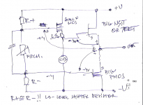
upper 1.take M2 schematic in Editor , print one sheet complete, one with all diodes deleted ( thinking of both 1N4148 and LM385) ; take that one without diodes and re-read what I wrote about biasing mech. and think - simply without AC signal going in; you'll grasp what's happening in DC domain
it's late , I was sleeping, damn dog which owns me is free enough to bark whenever she wants ..... so I found a reason to take book again, and also to check Greedy Boyz .... so I'm somewhat lazy to re-check what I drew and wrote ........ but somehow I'm doubting that I'm able to explain it better and clearer; maybe will check in the morning ; just to be nitpicky - beneficiary for future - "page X post" means nothing - every Greedy Boy is using different Browser, with differently set number of posts per page ; go figure - maybe I have entire thread as one page ?
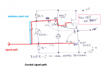
- when you grasped DC domain and understood how M2 is biased .......... think about AC domain; signal is pushing/pulling one end of big cap between gates , practically pushing/pulling one gate
- cap is acting as solid stainless steel rod between gates; no AC signal is able to change rod length ; take it as that cap is simply pumped with DC and that only biasing mechanism is able to change that amount of pumped DC/length of rod
- when you got that - imagine what is happening without any diode , if one is pushing 50Vpp in amp, while autoformer is amplifying that 6 times ? - how high and how low those puny output gates are going to be pushed?
-when you got that - look at full schematic and see which 1N4148 diodes are clamping gates (to positive rail) for positive overdrive, which 1N4148 diodes are are clamping gates (to negative rail) for negative overdrive
-when you got that - take that LM385 zeners are here "just in case" of any eventuality Gremlins ( stupid user) can think of - when voltage across source resistor can reach safe voltage for optodiode ; they're working great, but they're also fast to die, if voltage peak across them is too high and too long
lower 1. whenever you see (not just in M2 or LuDEF) big cap or caps or caps combined with parallel resistors between two output gates - understand it/them as stainless steel rod between those gates, pumped with DC, and AC can't change a iot of rod length; simple as that
lower 2. all plain zeners being gate(s) flyback/overdrive protection thingies; all LM385 being Anti-Gremlin protection for optodiodes
hope that I helped some; back to book and zzzzzzz ; she can bark again, I don't care
upper 1.take M2 schematic in Editor , print one sheet complete, one with all diodes deleted ( thinking of both 1N4148 and LM385) ; take that one without diodes and re-read what I wrote about biasing mech. and think - simply without AC signal going in; you'll grasp what's happening in DC domain
it's late , I was sleeping, damn dog which owns me is free enough to bark whenever she wants ..... so I found a reason to take book again, and also to check Greedy Boyz .... so I'm somewhat lazy to re-check what I drew and wrote ........ but somehow I'm doubting that I'm able to explain it better and clearer; maybe will check in the morning ; just to be nitpicky - beneficiary for future - "page X post" means nothing - every Greedy Boy is using different Browser, with differently set number of posts per page ; go figure - maybe I have entire thread as one page ?
- when you grasped DC domain and understood how M2 is biased .......... think about AC domain; signal is pushing/pulling one end of big cap between gates , practically pushing/pulling one gate
- cap is acting as solid stainless steel rod between gates; no AC signal is able to change rod length ; take it as that cap is simply pumped with DC and that only biasing mechanism is able to change that amount of pumped DC/length of rod
- when you got that - imagine what is happening without any diode , if one is pushing 50Vpp in amp, while autoformer is amplifying that 6 times ? - how high and how low those puny output gates are going to be pushed?
-when you got that - look at full schematic and see which 1N4148 diodes are clamping gates (to positive rail) for positive overdrive, which 1N4148 diodes are are clamping gates (to negative rail) for negative overdrive
-when you got that - take that LM385 zeners are here "just in case" of any eventuality Gremlins ( stupid user) can think of - when voltage across source resistor can reach safe voltage for optodiode ; they're working great, but they're also fast to die, if voltage peak across them is too high and too long
lower 1. whenever you see (not just in M2 or LuDEF) big cap or caps or caps combined with parallel resistors between two output gates - understand it/them as stainless steel rod between those gates, pumped with DC, and AC can't change a iot of rod length; simple as that
lower 2. all plain zeners being gate(s) flyback/overdrive protection thingies; all LM385 being Anti-Gremlin protection for optodiodes
hope that I helped some; back to book and zzzzzzz ; she can bark again, I don't care
Last edited:
maybe some of pics I posted in #178 and #179 : Babelfish XA252 / Babelfish XA252 SIT / Babelfish XA252 SET , could act as crystallization particle .........
Thanks ZM for the additional hints. I will look it over tomorrow. It is starting to make sense but want to look at it with fresh eyes. Can’t process anything right now.
- Home
- Amplifiers
- Pass Labs
- LuDEF