Well, I'm happy to report after much trial and experimentation that it is indeed possible to get decent h3 performance out of LTP. I haven't found any hard and fast rules, it just takes a lot of trial and error with different tube types and op points.
For a 2-stage LTP into LTP like the tubelab AB2 thread, I did find a couple of ways to minimize h3 and distortion in general. One is to use triode-connected high gm pentodes, particularly for the second stage. The other is to use higher gain tubes than you need and apply NFB from the 2d stage output to the unused 1st stage input.
For a 2-stage LTP into LTP like the tubelab AB2 thread, I did find a couple of ways to minimize h3 and distortion in general. One is to use triode-connected high gm pentodes, particularly for the second stage. The other is to use higher gain tubes than you need and apply NFB from the 2d stage output to the unused 1st stage input.
dgta,
Is there a good engineering reason why you couldn't just use a concertina? This isn't at all a criticism of anyone who has used an LTP. LTPs can simplify PS design. I just would like to think that your decision wasn't a product of group think and was logic based.
Is there a good engineering reason why you couldn't just use a concertina? This isn't at all a criticism of anyone who has used an LTP. LTPs can simplify PS design. I just would like to think that your decision wasn't a product of group think and was logic based.
No good engineering reason I couldn't use ANY topology, within reason. In fact I have a Williamson amp I designed and built a few years ago that measures and sounds excellent. No issue at all.
I am exploring various topologies, etc. at all times simply because this is a hobby and I enjoy learning what can be done with each topology, tube type, etc. etc.
At this point I do have a couple LTP circuits that do better (gain/distortion) than my best Williamson design, but that can change at any time as I spend more time researching each.
Every stage and component will introduce some imbalance one way or another. Some have very high imbalance like a totem pole output as compared to splitter, choosing one type over another does not help. Even when it's a PP amp, a better approach to reduce H3 would be to include some type correction ability, in addition to GNFB, you'll be surprised of the difference in the H3 result in output (ie. according to sim), actually should able to hear the difference too, like H3 sounds harsh? You may get more H3 in the front end, splliter but it's the resultant H3 in the output that matters.
I think the take-away message here is that both grids in a triode LTP should see consistently low impedance to ground if the stage has much gain. You would need a four-gang input level control to balance miller effect in a stereo amp with high-gain triode LTP input stages. It's better to simply ditch the input level control and rely on the preamp's low output impedance.
Hi Mike,
You mean control level at the output ?
I don't know enough to reword Tubelab's post. My take away message was that if the two sides of the pair aren't fairly well balanced there is measurable distortion that arises directly because of it. Thinking about that, if I'm using a 100K pot as input level control, where do I set the grid on the grounded side? 50K because it's a sort of average? or at something near where my usual listening level is? or where the worst distortion occurs if it's not? Thinking that way, I figured the easiest solution would be to have both impedances equal and moving together, and then wondered if there was any reason why it wouldn't be a good thing to do (besides the extra expense of the ganged pot).
The maximum output resistance of a 100k pot is 25k, not 50k. However, the source impedance of the preceding amplifier remains unknown. A fair compromise would be to use the 100k pot and follow it with a 10k series resistor, for example. You source resistance now varies from 10k up to 35k (plus the preceding stage output impedance). On the second grid use a 22k series resistor, which is a reasonable average.if I'm using a 100K pot as input level control, where do I set the grid on the grounded side? 50K because it's a sort of average?
Last edited:
If I measure the resistance from grid/wiper to ground with the level turned right down , it's 0.2 Ohms, so zero. If I measure the resistance at full volume it's 100K. I don't understand where the 25K is from. Are you making an assumption about the probable source impedance?
The rest of it I think I see. The passive grid is not fed by an external device so you have to compensate for the lack of parallel impedance. Yes?
The rest of it I think I see. The passive grid is not fed by an external device so you have to compensate for the lack of parallel impedance. Yes?
Yes, he is. Merlin is implying that IF the source impedance is zero, then effectively both ends of the pot are at AC ground and your max Z is 25k.
Whether that's a fair assumption is up to you. Probably an OK assumption if you're driving it with a well buffered solid state device.
Whether that's a fair assumption is up to you. Probably an OK assumption if you're driving it with a well buffered solid state device.
...if I'm using a 100K pot as input level control, where do I set the grid on the grounded side?
If this putative triode LTP is the input stage of a power amplifier, then the grid opposite the input side is either directly grounded or tied to a feedback divider with very low impedance to ground. A 100K input level control at the input side grid, with the wiper centered, amounts to a pair of 50K resistors in parallel to AC ground. One of those resistors goes to a real ground, while the other sees a (nearly) virtual ground due the preamp's nearly zero output impedance. This 25K impedance is high enough to turn miller effect into a significant problem. Does that help?
Yes, he is. Merlin is implying that IF the source impedance is zero, then effectively both ends of the pot are at AC ground and your max Z is 25k.
Whether that's a fair assumption is up to you. Probably an OK assumption if you're driving it with a well buffered solid state device.
Yes. I get it now. Thanks !
If this putative triode LTP is the input stage of a power amplifier, then the grid opposite the input side is either directly grounded or tied to a feedback divider with very low impedance to ground. A 100K input level control at the input side grid, with the wiper centered, amounts to a pair of 50K resistors in parallel to AC ground. One of those resistors goes to a real ground, while the other sees a (nearly) virtual ground due the preamp's nearly zero output impedance. This 25K impedance is high enough to turn miller effect into a significant problem. Does that help?
Yes , I think so -
Remember, my question started with Tubelab's post in which he mentions balance, not low impedance , and I didn't want to jump from one boat to the other. (I figure I don't need to rethink anything he says, I just need to try to understand it.)
But I think I understand now how both things apply. The outcome of Tubelab's post is that if the Miller C problem is mirrored equally on the other side of the differential stage then the effect is canceled at the output, and what you're saying is that to the degree the impedance is kept low, to that degree the problem doesn't arise in the first place. Have I got it right?
Well, it matches my understanding at least! I generally avoid triode input stages where a lot of gain is required, but low-gain triode LTPs can be useful as direct-coupled power amplifier input stages.
Good to know, thanks!
Off topic I guess but your comment got my attention. When you need higher gain what do you use, pentode? sand? I'm just starting to play with pentodes a bit, and the same with transistors.
Off topic I guess but your comment got my attention. When you need higher gain what do you use, pentode? sand? I'm just starting to play with pentodes a bit, and the same with transistors.
Pentodes or cascoded triodes can work well. Lately, I've been fooling around with direct-coupled PNP transistors in circuits resembling Frank Blöhbaum's multiplied transconductance amplifier (MTA). Perhaps there's a related thread in this forum.
Thanks for the link. Interesting stuff. I've been trying things with Rod Coleman's shunt cascode circuit in a phono stage. Just got the latest version running last night. It looks to my untrained eye like similar turf.(ie gm amp). Now that it's up and running I'm going to listen for a few weeks while I go back to a pentode project. Guess we're covering similar ground. Jeeze, I wonder if everybody here is . 🙂
The 12AT7 is notorious for distortion in SE mode (it is a non-linear mixer tube after all), but it has a gm curve versus current that is more amenable to CCS tailed LTP use.
The gm curve versus Ip looks more like a linear ramp (which summed with its flipped around version, comes closer to constant gm)
http://frank.pocnet.net/sheets/093/1/12AT7.pdf
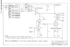
I recently clipped together a version of Gordon Rankin's Bugle and was surprised at the clean sound. Would the GM vs Ip curve sum in a similar way for an SRPP circuit?
Attachments
A 6072 is essentially a 12AY7.
I use a 12AY7 with an LM334 current sink, as a cathode coupled phase inverter for some of my push pull amplifiers.
Sounds good to me.
I use a 12AY7 with an LM334 current sink, as a cathode coupled phase inverter for some of my push pull amplifiers.
Sounds good to me.
SRPP is a class A P-P circuit, so the gm's should effectively sum. 6072/12AY7 doesn't have quite as flat a gm ramp as 12AT7 (versus current), it's a constant Mu tube, but it straightens to a decent ramp at higher current.
A cheap tube that gives you a 12AT7 like triode (plus a 5W frame grid pentode) is 6KR8 (and 6LQ8 is similar). Good for a LTP splitter followed by a driver tube stage. The frame grid pentode in the 6KR8 and 6LQ8 also makes a decent constant Mu 33 or Mu 50 triode if wanted. (tubes were on the $1 list once)
Check the ramping gm of the 6KR8 versus current, last page:
https://frank.pocnet.net/sheets/135/6/6KR8A.pdf
These kind of tubes are high on 2nd harmonic, but low on 3rd harmonic. 2nd H cancels in a class A LTP or SRPP.
The floating paraphase splitter also allows one to select a tail resistance that will cancel 3rd harmonic over some limited signal level range. (possible for low signal level splitting duty)
If you can find a thermionic diode, or diode wired triode, that has the same Ri at the operating tail current, it can replace the tail R for wide range 3rd harmonic cancellation. (think of the Akido design, where a non-linear load and matching non-linear drive tube give linear results)
And then there are beam deflection tubes like 6JH8 which have linear deflector function. They need some small Mosfet cascodes above them to get high gain though. A paraphase or floating paraphase circuit for the deflectors (to put equal magnitude signals on both deflectors) will give the best results for low odd harmonic.
Last edited:
Thanks for posting that. I downloaded that image from the net without even looking. Assumptions !
Shown here with 12AT7.
I've been messing around with feedback lately and growing used to the sound, was a bit surprised to hear a similar sort of very clean, clear if slightly lean sound out of the SRPP.
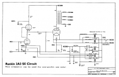
I listened to quite a few SRPP circuits in commercially built amps when they were an often talked about thing and never liked what I heard very much, but the Baby O' had some praise from a friend so put a reasonably close version together. It doesn't have many hours on it so not sure if it would hold up long-term but so far it's quite impressive.
Shown here with 12AT7.
I've been messing around with feedback lately and growing used to the sound, was a bit surprised to hear a similar sort of very clean, clear if slightly lean sound out of the SRPP.
I listened to quite a few SRPP circuits in commercially built amps when they were an often talked about thing and never liked what I heard very much, but the Baby O' had some praise from a friend so put a reasonably close version together. It doesn't have many hours on it so not sure if it would hold up long-term but so far it's quite impressive.
Attachments
For SRPP there is no constant current regulator in play like for the LTP, so it is possible that constant Mu tubes like the 6072/12AY7 will give lower 3rd harmonic. Should test with a simulator I guess.
In that case, there are similar triode plus frame grid pentode tubes from the old $1 list.
6LY8, 6KV8, 6JT8 and 6HZ8 have constant Mu triodes and high gm pentodes.. All, including the previous 6KR8 and 6LQ8 are 9DX based, so are interchangeable socket wise at least.
In that case, there are similar triode plus frame grid pentode tubes from the old $1 list.
6LY8, 6KV8, 6JT8 and 6HZ8 have constant Mu triodes and high gm pentodes.. All, including the previous 6KR8 and 6LQ8 are 9DX based, so are interchangeable socket wise at least.
Last edited:
If you can find a thermionic diode, or diode wired triode, that has the same Ri at the operating tail current, it can replace the tail R for wide range 3rd harmonic cancellation. (think of the Akido design, where a non-linear load and matching non-linear drive tube give linear results)
After reading about the Axiom 300B amp, I built a much much simpler 2 stage amp with a damper diode as the 6336 output triode's cathode resistance. It sounded very good.
- Home
- Amplifiers
- Tubes / Valves
- LTP and H3 distortion