Hey all...
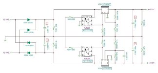
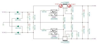
My current project has a controller board with three voltage regulators, two LT1963's and one LT3015 negative regulator. The "problem" which isn't a real problem is that both 1963 positive regulators are not completely shutting down when the shutdown pin is low. I get about 275 mV @ 170 uA instead of the 0 volts and "less than one microamp" it is supposed to show. Now I know that nothing will run on voltage that low but it seems weird that it doesn't go to zero volts like the LT3015 does. Is that just a quirk of the LT1963?
Here's that part of the PCB:

Any thoughts?
Mike
My current project has a controller board with three voltage regulators, two LT1963's and one LT3015 negative regulator. The "problem" which isn't a real problem is that both 1963 positive regulators are not completely shutting down when the shutdown pin is low. I get about 275 mV @ 170 uA instead of the 0 volts and "less than one microamp" it is supposed to show. Now I know that nothing will run on voltage that low but it seems weird that it doesn't go to zero volts like the LT3015 does. Is that just a quirk of the LT1963?
Here's that part of the PCB:
Any thoughts?
Mike
Attachments
I'd connect the voltmeter probes across R205 during shutdown and verify that the "S" pin voltage really is less than 249 millivolts. Note that (30uA * R205) exceeds the spec, this could become problematic.
Yes that's odd. Have you tried to jumper R205 directly to the adj pin gnd?
Are the grounds of the adj pin and R205 separated by a piece of track that carries output current?
Another consideration is that there's some ripple going trough the opto even when off; is the residual output pure DC or rectified ripple?
Maybe scope the shutdown pin (and output) when off.
Jan
Are the grounds of the adj pin and R205 separated by a piece of track that carries output current?
Another consideration is that there's some ripple going trough the opto even when off; is the residual output pure DC or rectified ripple?
Maybe scope the shutdown pin (and output) when off.
Jan
If Jan's recommended oscilloscope test reveals 0.000V across R205 at all horizontal sweep settings from 20 msec/div to 20 nsec/div, with the scope ground clip attached to the LT1963's G pin,
and if shorting the LT1963's S pin straight to its G pin doesn't let the +12V rail drop to 0.000V { bypassing Jan's hypothesis of ground-isnt-ground },
then you've either got a bad LT1963 chip, or there is some other circuit entity sourcing current into the +12V rail.
If you don't want to spend the money to replace the LT1963 until last, when it's unequivocally proven to be the problem, then you can pursue tactics to find "some other entity sourcing current into the +12V rail". Such as looking at the schematics of everything connected to the +12V rail and finding all components connected to +12V. Then probe those components and their nearby neighbors, looking for voltages ABOVE the +12V rail voltage which post #1 says is +0.275 volts. Signal XYZ is above the +12V rail? Then XYZ is pulling up the +12V rail.
I think he said it's both regs that show this behaviour, which makes it more intriguing.
What are the chances both are bad.
But assuming both parts of the PCB are laid out similarly, that's a pointer.
Michael can you perhaps show a pic of the board?
Jan
What are the chances both are bad.
But assuming both parts of the PCB are laid out similarly, that's a pointer.
Michael can you perhaps show a pic of the board?
Jan
I'm in the process of gathering pics, info, and measurements...but life keeps getting in the way of my hobby...so when I get my time, energy and motivation to coincide I'll post it all, probably tomorrow. Thanks for the help so far guys.
In the mean time, here's the KiCad folder with schematics and boards...and just a warning, I had a batch of them made to check out and did find so mistakes that I already kludged away, and verified that it all works as expected except for this issue. I'm sure there will be further questions, so I'll check in later...right now I'm being summoned...over and out!
Mike
Attachments
Last edited:
Are the grounds of the adj pin and R205 separated by a piece of track that carries output current?
...if shorting the LT1963's S pin straight to its G pin doesn't let the +12V rail drop to 0.000V { bypassing Jan's hypothesis of ground-isnt-ground }
Please explain: does that mean GND of the load should be wired separately back to some star point upstream, or should we avoid exactly this to prevent ground-isn't-ground?
LT1963 compares its "S" against ("G" + 0.25V). Those are pins of the LT1963 integrated circuit. So you want to measure what the LT1963 is seeing: the voltage between "S" and "G". If there is some funny business going on elsewhere in the ground network, as hypothesized in post #4 of this thread, you had better look where the LT1963 is looking: at its "G" pin.

"A .zip file with 20 other .zip files - really ..."
It is the KiCad directory for the circuit board having the issue...when I open it there's all of the KiCad files intact. So I'm not sure what could be wrong. I used 7-zip to compress it.
Ah...I took another look, you're talking about the backup directory I should have left out...whoops, my bad.
Mike
Last edited:
Michael, if I ask if you could post the layout so we could take a look and possibly help you, and you send me a zip containing another 20 zips, you really think I go through all this in a hope to find something useful?
I have a life too.
Jan
I have a life too.
Jan
I stripped out all of the KiCad stuff that has nothing to do with PCB fabrication, resulting in this set of only Gerber files in .zip format. If anyone wants to view it carefully (not me, thank you), these will read in your Gerber Viewer software. I tried the free, runs-in-your-browser Gerber viewer, which you don't have to install or to give your email address, at
www.pcbxprt.com (yes remember to type the www)
and these Gerbers read in just fine.
www.pcbxprt.com (yes remember to type the www)
and these Gerbers read in just fine.
Attachments
They all read perfectly fine on my end using KiCad...I don't need an external viewer. I'm going to go get some measurements shortly...I'll be back!
Just a thought...If I try to open the Gerbers by directly clicking on them, or opening them from any location other than the "Documents" directory where KiCad expects them to be it doesn't work. The directory must reside in the documents folder, and must be accessed through the KiCad program or it won't work. I'm using Widows10 if it matters.
Mike
Last edited:
I always start GerbView and open the directory with the Gerbers from there - that way they can be in any location...
OK I'm back...
Sorry it took so long, I've been dealing with some unexpected surprises the last couple of days.
Most of y'all's suggestions I already tried, but I went back and checked again to be sure. First, a direct short between pins one and three (shutdown and ground, respectively) made no change with about a quarter of a volt when unloaded appearing at the output. I also couldn't find any voltage drops anywhere on the ground plane, and no voltage shown between the ground pin (3) and any other point on the board even when fully loaded. My 100Mhz scope showed nothing but nice DC with a very, very small bit of noise that I couldn't be sure wasn't the noise floor of the scope, and not a hint of 60Hz feedthrough in the outputs. I did go ahead and replace both 1963's just to see if they were the problem because I remembered that during my initial testing I connected the power transformer up incorrectly once and thought maybe that could be the problem...but that didn't change anything, just wasted my time and two regulator chips. I've checked everything I could think of and followed up on all of your suggestions, and I still can't find an explanation. When fully loaded the bleed-through voltage drops to about .02 volts and current is only a few microamps, so it's not actually a problem operationally, but it isn't nominal either. I'm thinking that if no solution can be found, I'll put a VOM1271/MOSFET switch before the regulator and tie the shutdown pin to the input pin and call it a day.
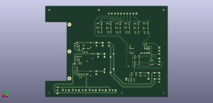
Here are pics of the front and back sides taken from the 3-D viewer in KiCad if it helps.
Oh yeah...In case anyone notices, there were errors in the boards I had fabricated...there's a trace missing between pins 2 and 3 on PRV205, and the entire section with the MOSFETs and TL431s near the ten pin connector got messed up somehow and required some "fixing" to get it working right...but it does all work exactly as designed with the exception of that one little gremlin.
Once I get everything figured out I'll have new boards fabricated...if anyone is curious I can elaborate on what I'm building, but I was planning to do that anyway once the whole thing is complete.
Mike
Sorry it took so long, I've been dealing with some unexpected surprises the last couple of days.
Most of y'all's suggestions I already tried, but I went back and checked again to be sure. First, a direct short between pins one and three (shutdown and ground, respectively) made no change with about a quarter of a volt when unloaded appearing at the output. I also couldn't find any voltage drops anywhere on the ground plane, and no voltage shown between the ground pin (3) and any other point on the board even when fully loaded. My 100Mhz scope showed nothing but nice DC with a very, very small bit of noise that I couldn't be sure wasn't the noise floor of the scope, and not a hint of 60Hz feedthrough in the outputs. I did go ahead and replace both 1963's just to see if they were the problem because I remembered that during my initial testing I connected the power transformer up incorrectly once and thought maybe that could be the problem...but that didn't change anything, just wasted my time and two regulator chips. I've checked everything I could think of and followed up on all of your suggestions, and I still can't find an explanation. When fully loaded the bleed-through voltage drops to about .02 volts and current is only a few microamps, so it's not actually a problem operationally, but it isn't nominal either. I'm thinking that if no solution can be found, I'll put a VOM1271/MOSFET switch before the regulator and tie the shutdown pin to the input pin and call it a day.
Here are pics of the front and back sides taken from the 3-D viewer in KiCad if it helps.
Oh yeah...In case anyone notices, there were errors in the boards I had fabricated...there's a trace missing between pins 2 and 3 on PRV205, and the entire section with the MOSFETs and TL431s near the ten pin connector got messed up somehow and required some "fixing" to get it working right...but it does all work exactly as designed with the exception of that one little gremlin.
Once I get everything figured out I'll have new boards fabricated...if anyone is curious I can elaborate on what I'm building, but I was planning to do that anyway once the whole thing is complete.
Mike
Attachments

Last edited:
- Home
- Amplifiers
- Power Supplies
- LT1963 unexpected results