Not to argue, just that all the little stuff adds up to a better system. A little performance boost here and there adds up to a lot of performance boost. And in these days of the sum of decades of learning, it's going to take a lot of discussion to find some new effect.
I am a professional robotics technician, not an audio tech. The systems are similar but do have minor differences. I came here to learn some stuff about improving fidelity. In the past, the pros kept "trade secrets" and showed off their superior system. These days we seem to openly discuss about anything.
I did a test with the TDA2030 dc amp on, for some reason, (virtual short ?) the driver WAS heavily damped at "zero" signal, and I could not easily detect any change by finger tapping. I assumed at signal velocity, the voice coil would generate much more back-emf, and the parallel resistor would parallel amp Z.
I'd have to say yea, at signal velocity damping would improve with the Lpad.
I only meant to tap in a little thought, and not a big OT sidestep. Something fun to look at though, an Lpad advantage. Since I'm new here, I'll let you all know you can trust most of my knowledge, but I do run a 90 to 95% average.
Here ya go, the last paragraph here says, as I did, the parallel resistor WILL have some beneficial effect but the dynamic impedance of the dc amplifier will be the usual lower impedance. The kick drum pulse type situation would see the benefit of the parallel resistor in an Lpad.
http://en.wikipedia.org/wiki/Electrical_characteristics_of_dynamic_loudspeakers
Last edited:
Thanks Wavewhipper, and I found the post midrange refers to.
As Rod was saying, the resistor affects the damping of the woofer. The damping is also seen as the Q of the rolloff. When a filter, (whether it be an LC or a woofer/cabinet) is underdamped, it rings. Imagine the level being increased partially by the fact that it continues longer than the original. This is normal, as in it will happen with a woofer in a certain size of box even if it is fed from a short circuit. Up to a point it isn't necessarily audible. What counts at the end is how much rather than the fact that it happens or even how it happens (by resistors or otherwise).
As Rod was saying, the resistor affects the damping of the woofer. The damping is also seen as the Q of the rolloff. When a filter, (whether it be an LC or a woofer/cabinet) is underdamped, it rings. Imagine the level being increased partially by the fact that it continues longer than the original. This is normal, as in it will happen with a woofer in a certain size of box even if it is fed from a short circuit. Up to a point it isn't necessarily audible. What counts at the end is how much rather than the fact that it happens or even how it happens (by resistors or otherwise).
Check out the following papers. They go into this topic (and others) in fairly good detail.
Thanks Wayne. That is what I observed by schematic and physical observations about these crossover circuits, and had been teetering about how deep to go into it. In reality, that is a light simple explanation, these things can get deep 🙂.
In my case, I lucked out and a 2db Lpad smoothed out my midrange or just happened by pure luck to throw some peaks where they were needed, I haven't run a scan on it yet, all by ear.
I sort of figured the active crossover isn't quite the easy out it is hooped up to be.
In my case, I lucked out and a 2db Lpad smoothed out my midrange or just happened by pure luck to throw some peaks where they were needed, I haven't run a scan on it yet, all by ear.
I sort of figured the active crossover isn't quite the easy out it is hooped up to be.
Last edited:
I was also a little concerned about some easy find crossover types with more and more inductors. I was thinking, where does the stored energy go in these things ? Ugh, I'm gonna have to find out.
Still for $70 each my DIY speakers are much better than my $150 each Pro LX550 speakers. Not really fair since it's a 10 inch 3 way vs a 5" two way with an exceptionally nice tweeter and Kevlar woofer. That's what ya get for throwing the work on some else for a cheap price.
So my vote, is now stronger towards use the Lpad instead of a single resistor.
Last edited:
So my vote, is now stronger towards use the Lpad instead of a single resistor.
It's not that easy.
If I can go with no crossover, I will go with no crossover, but usually I cannot, but I tried.
If I can go with no attenuation, then I will. I will try to find matched woofer, suitable FR or even multi amping to avoid attenuation to the tweeter. And because there will always be compromises, the conclusion can only be drawn after side by side comparison of the various options.
Resistor at the input of the HF filter is my favorite, especially with top tweeters with good dispersion and extended response. But there is limitation to the maximum attenuation that can be achieved. Above 10R the sound starts to become "dead" (depends on tweeter and amp). If more attenuation needed, I use L-PAD with series resistor no more than 1R and shunt resistor no less than 15R. Of course I don't use series R alone next to the tweeter. It doesn't sufficiently attenuate and the effect is terrible.
I have tried to compare L-PAD with T-PAD because it was known that T-PAD is better, but I couldn't find exact match so I ended up with series resistance being lower in L-PAD and (so) of course the L-PAD sounded better than the T-PAD. But that's not objective comparison.
Imo, the best speaker should NOT use L-PAD. We use it only because we have limited option.
Selamat sore jay,
I just have set up my speakers with 15R alone, cause >l-<pad gave nothing good for my own problems. but have to say I d'ont know th R of the driver and don't have micro for measurement : see my thread "Acoustical filter for tweeters".
I just have set up my speakers with 15R alone, cause >l-<pad gave nothing good for my own problems. but have to say I d'ont know th R of the driver and don't have micro for measurement : see my thread "Acoustical filter for tweeters".
Funny, I haven't heard mention of T pads for a long time, I'll review them. Thanks for the mention.
Selamat sore jay,
I just have set up my speakers with 15R alone, cause >l-<pad gave nothing good for my own problems. but have to say I d'ont know th R of the driver and don't have micro for measurement : see my thread "Acoustical filter for tweeters".
Hi there Eldam 🙂
Now you know the effect of resistor at the input of the tweeter filter. I think your speaker has terrible tweeter response especially at the upper highs. A sharp peak, even above 20kHz is "audible". You may not be able to "hear" it, but in the long run they kind of fatiguing.
A resistor at the input has the effect of "tilting down" the upper end respond. This will solve many issue with tweeter at the upper end. A tilting down response especially with small 2-way will also give a perceived better balance and coupled with non existence of treble issue will give you a disappearing act.
A notch filter at tweeter frequency is very dangerous. It must be done carefully with ARTA and/or good ears. Or you will ruin the vocal neutrality.
Don't know your amp, but you can try current feedback amps for their excellence at top ends (search for VSSA as a good example of CFA)
Thank you Jay,
My amp is a Chord. the tweeter is aluminium material, Ferrofluided and go as high at 30 Khz...with a big mechanical dip at 20K maid by an acoustical filter in front of it (maid by Phil Jones the designer) and a big peak just above ..it's not a peak it's the kerinci !
15R alone is a little too much I have to try for a final test a last L-Pad : 3.5 db which is R1 with 2.7R and R2 with 15R.
Thank you Jay,
My amp is a Chord. the tweeter is aluminium material, Ferrofluided and go as high at 30 Khz...with a big mechanical dip at 20K maid by an acoustical filter in front of it (maid by Phil Jones the designer) and a big peak just above ..it's not a peak it's the kerinci !
15R alone is a little too much I have to try for a final test a last L-Pad : 3.5 db which is R1 with 2.7R and R2 with 15R.
What do you mean with "a little too much" with 15R? Are you talking about:
(a) Too much attenuation of the treble?
(b) Lost of coherence? (If so, replace the 6uF after the resistor with 1.8uF)
(c) Lack of sparkle or "dead" sound? (If so, combine the 10R at the input with L-PAD made of 1R and 15R)
What do you mean with "a little too much" with 15R? Are you talking about:
(a) Too much attenuation of the treble?
(b) Lost of coherence? (If so, replace the 6uF after the resistor with 1.8uF)
(c) Lack of sparkle or "dead" sound? (If so, combine the 10R at the input with L-PAD made of 1R and 15R)
13R maid with 12+1 in serie was not enough because the brighness peak can be heard. 15R is better regarding the peak of brighness but the voice and the middle is too muffled ! So a) and a little b) too because mostly heard in the middle (voices are too muffled and heavy...they have to be more pristine, clearer...not so warmer). Maybe your c) description is what i want to write : muffled=dead sound like a cover plate on a nasi goreng : you don't hear the oils boils...
Wich 6uF are you talking about ? The 8 uf // 6 uF of the first cellul in the 4° order filter ?
But there is so little difference in DB attenuation between 13R & 15R : 0.7 DB. And the initial tweeter attenuation is 10R//1uF in serie. Without the cap is better every where but one exception is near than the best results I test. It's : 1R in serie with the initial 10R//1uF !
So I have to test before your C) : Initial R1 10R without the //1uf and R2 L-Pad with 16R (15+1 serie).
Thnak you
Hope no Hijack this thread.
Thank you Jay,
My amp is a Chord. the tweeter is aluminium material, Ferrofluided and go as high at 30 Khz...with a big mechanical dip at 20K maid by an acoustical filter in front of it (maid by Phil Jones the designer) and a big peak just above ..it's not a peak it's the kerinci !
There is no benefit of going up to 30KHz if below it you have peak/kerinci!
A peak after a notch is often a sign of imperfect notch, probably because the peak is so wide (low Q) while the notch is naturally sharp. If the the mechanical notch can be removed, you may want to try conventional notch. Not expensive as parallel notch will need around 0.2mH and 220nF.
Or you can modify the mechanical notch, just like you do the toilet tissue thing 😀
Hope no Hijack this thread.
I believe this is the down to earth answer to what OP was seeking.
13R maid with 12+1 in serie was not enough because the brighness peak can be heard. 15R is better regarding the peak of brighness but the voice and the middle is too muffled ! So a) and a little b) too because mostly heard in the middle (voices are too muffled and heavy...they have to be more pristine, clearer...not so warmer). Maybe your c) description is what i want to write : muffled=dead sound like a cover plate on a nasi goreng : you don't hear the oils boils...
Wich 6uF are you talking about ? The 8 uf // 6 uF of the first cellul in the 4° order filter ?
But there is so little difference in DB attenuation between 13R & 15R : 0.7 DB. And the initial tweeter attenuation is 10R//1uF in serie. Without the cap is better every where but one exception is near than the best results I test. It's : 1R in serie with the initial 10R//1uF !
So I have to test before your C) : Initial R1 10R without the //1uf and R2 L-Pad with 16R (15+1 serie).
You should not write 15+1=16R as the L-PAD has bigger effect at attenuation than series R at the input, or shunt R cannot be added with series R in a L-PAD (it is simply a voltage divider network).
The (C) is like I posted before, that above 10R at the input the sound tend to become "dead". The biggest I have experienced is 12R2. You can replace the series R at the input with an L-PAD, but L-PAD is worse (also the "dead" sound) so the maximum attenuation without deadening the sound is the combination of series R at the input around 10R and the L-PAD with series resistance no more than 1R.
The (B) is, yes, the 1.8uF is to replace the 6uF so to reduce from total 14.2uF to 10uF. This is to restore the phase coherence of the original network (which was changed with your 15R modification)
Ok understand know : 1 ohm is the serie added resistor to the initial 10 ohm and 15 ohms is the shunt value of the L-Pad (=R2 in the L-Pad) shematic...
Do I have to test with the 1uf// to the 10 ohms too ? No matter if the serie added 1 ohm is at the beggining of the filter (in front of or just after the 10R//1uF and th R2 shunt at the end near the driver ?
Of course my toilett tissue is branded with the name: "Can Peak Attenuator?"
Do I have to test with the 1uf// to the 10 ohms too ? No matter if the serie added 1 ohm is at the beggining of the filter (in front of or just after the 10R//1uF and th R2 shunt at the end near the driver ?
Of course my toilett tissue is branded with the name: "Can Peak Attenuator?"
Ok understand know : 1 ohm is the serie added resistor to the initial 10 ohm and 15 ohms is the shunt value of the L-Pad (=R2 in the L-Pad) shematic...
Do I have to test with the 1uf// to the 10 ohms too ? No matter if the serie added 1 ohm is at the beggining of the filter (in front of or just after the 10R//1uF and th R2 shunt at the end near the driver ?
The 1uF effect is more or less to increase the top end of the treble response. It seems that the top end is problematic so I believe your ears that it was better without it. Besides, even tho this kind of network is considered "smart" by experts but believe me I'm against such network.
I think you got it wrong. What I mean is:
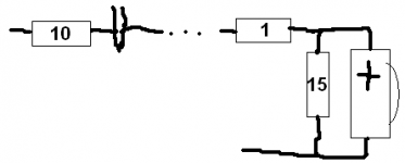
10R at the input (the 1uF removed), then next to the tweeter you have 1R (series) and 15R parallel (across plus and min of the tweeter)
Attachments
Thank you Jay,
Ok, The two resistors of the L-Pad need to be together.
I'm going to start it. Say to you tomorrow the result...
Ok, The two resistors of the L-Pad need to be together.
I'm going to start it. Say to you tomorrow the result...
For me phase is the most critical concern of speaker design. Assuming that the original has perfect phase coherence, then you may want to reduce the 14.2uF series capacitance. 1uF reduction I believe will not hurt, but you don't have many parts so forget such mod for the moment.
- Status
- Not open for further replies.
- Home
- Loudspeakers
- Multi-Way
- Lpad v single resistor