Once again, not all manufacturers made the EL34 the same. La Radiotechnique had the cathode and g3 connected to the same pin.
JJ calls the 6CA7 a power beam tube, I've have not seen those so cannot say they are a beam power tube or a true pentode.
This only suggests that who the manufacturer is can make a difference.
JJ calls the 6CA7 a power beam tube, I've have not seen those so cannot say they are a beam power tube or a true pentode.
This only suggests that who the manufacturer is can make a difference.
The original document by Schade - Beam Power Tubes, publication ST-59, March 1938, RCA.
page 155 mentions screen 10 to 20 volt below plate
page 160 in the document it mentions 10 to 15 Volts below plate to prevent secondary emission effects
page 169 mentions designed for screen to be between 250 and 300 V
Thank you.
For reference: http://www.tubebooks.org/tubedata/beam_power_tubes.pdf
155 and 160 do not say "screen" but "potential minimum" which is a very different thing.
169 does say 250-300 but that was "designed". Clearly some tubes are designed for other screen conditions, but 250V is enough to do some good, not enough to do great harm to electrodes, and was THE common supply in radios (the 'killer app' of tubes) before the hot-chassis era.
Attachments
Memory no longer what it once was, so you have to forgive my errors. At least I was able to point you in the right direction.
In my SE UL amplifier the screen is 20V below the plate and I'm happy with the performance.
In my SE UL amplifier the screen is 20V below the plate and I'm happy with the performance.
To give another example: Brimar's ECC81 has a Vhk of 250V whereas all the other ECC81 (12AT7) have a Vhk of 90V.
As far as I know the 12AT7/ECC81 Brimar Application Report of 1950 is the only document that shows a maximum cathode to heater voltage of 250V. So I would think that the report most likely is wrong on this.
Once again, not all manufacturers made the EL34 the same. La Radiotechnique had the cathode and g3 connected to the same pin.
Although the diagram on page 1 of this La Radiotechnique datasheet shows what you wrote, the diagram of the pin-out on page 4 does show g3 as a seperate pin. So I think that the diagram on page 1 is a mistake.
Did La Radiotechnique even manufacture EL34's? La Radiotechnique was part of the Philips Group. Most (or probably even all) members of the group did not manufacture all tube types themselves but had many of them them produced by other members of the group (who labelled them accordingly).
Datasheets and databooks contain more errors than one might think (and certainly more than I once thought). I've ploughed my way trough most of the "Electronic Tube Handbook Muiderkring" 17th edition from 1976 (known for their diagrams like for example the attached one for the 6N7, which by the way is faulty) and found many (!) mistakes in it. See: List of errors in Electronic Tube Handbook Muiderkring
Attachments
Last edited:
I only wish there were some large "Russian rod pentodes" for want of a completely accurate name.
They have no grid wires at all, so are they pentodes or beam tubes?
But in my own experiments with beam tubes like 6P30BR, I did indeed find an optimum Vg2, where the best compromise between THD and power, occurred when Vg2 was 20V below plate.
They have no grid wires at all, so are they pentodes or beam tubes?
But in my own experiments with beam tubes like 6P30BR, I did indeed find an optimum Vg2, where the best compromise between THD and power, occurred when Vg2 was 20V below plate.
PFL200,
Thanks for the file: EL34 Radiotechnique.pdf
That application schematic shows cathode and suppressor grid connected (to simplify the wiring).
But the actual pin-out on a lower page does show pin 1 suppressor, and pin 8 cathode.
Thanks for the file: EL34 Radiotechnique.pdf
That application schematic shows cathode and suppressor grid connected (to simplify the wiring).
But the actual pin-out on a lower page does show pin 1 suppressor, and pin 8 cathode.
EL506,
Thanks for the information on the JJ 6CA7.
I was able to confirm:
The JJ 6CA7 does have Beam Formers, and they are connected to Pin 1, and no internal connection to the cathode (Pin8).
The rest of the tube design causes the parameters to be very closely the same as an EL34 pentode . . .
so that it is a Plug in replacement for the EL34.
That means you can do a Plug and Play tube rolling listening session of a beam power tube and pentode, 6CA7 and EL34 (if you use self bias, should be OK, but check the cathode current; with fixed adjustable bias, set the bias to make the cathode current the same).
The same kind of Plug and Play tube rolling listening session can be done with a KT77 and EL34,
as long as you strap Pin 1 to Pin 8. Again, check the self bias voltages (for equal cathode current); and set the fixed adjustable bias voltages if needed to get the cathode current equal between KT77 and EL34.
So, tube roll a 6CA7, KT77, and EL34.
Beam Power, Kink-less Tetrode, and Pentode.
Happy tube rolling.
Happy listening.
Last edited:
On another note: Once I was at my wits end as one channel had some slight hum whereas the other was dead quiet. In the end I discovered attached document from Philips regarding the ECC83 (12AX7): the triode on pin 6,7,8 has the lowest hum.
Attachments
As far as I know the 12AT7/ECC81 Brimar Application Report of 1950 is the only document that shows a maximum cathode to heater voltage of 250V. So I would think that the report most likely is wrong on this.
....
Cannot see 250V being a typo of 90 / 100V.
There was a reprint of the 1950 report in 1952 which still has the same data. If it had been wrong then surely it would have been rectified.
I never cared too much for Muiderkring's books or designs due to having been caught out. Muiderkring was only a publisher for the Amroh parts and quality checking of their publication was far down on their list of priorities.
Last edited:
since i design and build my own power transformers, i make my psu, voltage doublers, this makes it very easy to feed G2 voltages in case of TV scanning tubes...
Pioneer, Sansui, Harman Kardon Citaton 2, Marantz 8 and Patrick Turner, used the full wave doublers a lot...
Pioneer, Sansui, Harman Kardon Citaton 2, Marantz 8 and Patrick Turner, used the full wave doublers a lot...
I'd suggest that any wiring or valve change you made to modify the pin allocation of the triodes may have achieved your hum improvement, rather than just the lower anode - heater capacitance afforded by one triode over the other due to wider novel spacing between pins 1 and 9 compared to pins 5 and 6.Once I was at my wits end as one channel had some slight hum whereas the other was dead quiet. In the end I discovered attached document from Philips regarding the ECC83 (12AX7): the triode on pin 6,7,8 has the lowest hum.
EL506,
Thanks for the information on the JJ 6CA7.
I was able to confirm:
The JJ 6CA7 does have Beam Formers, and they are connected to Pin 1, and no internal connection to the cathode (Pin8).
The rest of the tube design causes the parameters to be very closely the same as an EL34 pentode . . .
so that it is a Plug in replacement for the EL34.
That means you can do a Plug and Play tube rolling listening session of a beam power tube and pentode, 6CA7 and EL34 (if you use self bias, should be OK, but check the cathode current; with fixed adjustable bias, set the bias to make the cathode current the same).
The same kind of Plug and Play tube rolling listening session can be done with a KT77 and EL34,
as long as you strap Pin 1 to Pin 8. Again, check the self bias voltages (for equal cathode current); and set the fixed adjustable bias voltages if needed to get the cathode current equal between KT77 and EL34.
So, tube roll a 6CA7, KT77, and EL34.
Beam Power, Kink-less Tetrode, and Pentode.
Happy tube rolling.
Happy listening.
i make it a habit to connect pin 1 and 8 together, on the 6l6 family of tubes...
since i design and build my own power transformers, i make my psu, voltage doublers, this makes it very easy to feed G2 voltages in case of TV scanning tubes...
Pioneer, Sansui, Harman Kardon Citaton 2, Marantz 8 and Patrick Turner, used the full wave doublers a lot...
Neat idea. I use doubler and quad circuits to make ~300V for output, / 600V for the front end in my MA-1 designs from 120V transformers but I never thought of geting 150V from it as well since I build triode amps.
Now you have me wondering how it would work compared. It's not like I need more power though but 320V plate, 160V screen and ~2k2 load in push pull AB1 using my interleaved PT for OPT method might mean it'd be crap since the rp is so high compared to triode. Not like it would be hard to rig up though so hear it.
Maybe I should try it. I could just tap the mid point of the caps in the doubler for it.
EDIT: attached schematic
Attachments
Last edited:
yes, considering that 500-0-500 vac secondary is harder to do than winding a single 260vac winding to get to the same B+....insulations and economy are easily realized....
Neat idea. I use doubler and quad circuits to make ~300V for output, / 600V for the front end in my MA-1 designs from 120V transformers but I never thought of geting 150V from it as well since I build triode amps.
Now you have me wondering how it would work compared. It's not like I need more power though but 320V plate, 160V screen and ~2k2 load in push pull AB1 using my interleaved PT for OPT method might mean it'd be crap since the rp is so high compared to triode. Not like it would be hard to rig up though so hear it.
Maybe I should try it. I could just tap the mid point of the caps in the doublers for it.
EDIT: attached schematic
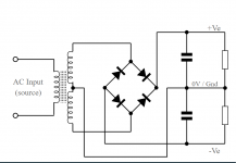
yes, you can even use a center tapped secondary winding, use a full wave bridge and use the center tap point with its own filtering for dc 1/2 of b+..
this is what i mean: if you make the - terminal at 0volts, then you can tap 1/2 B+, this is also possible for existing traffos on the market..
beware though, the schematic i got from the web had the fw rectifiers skewed 90 deg. clockwise.... 😀
Last edited:

Cannot see 250V being a typo of 90 / 100V.
There was a reprint of the 1950 report in 1952 which still has the same data. If it had been wrong then surely it would have been rectified.
There are many types of mistakes. Someone might have seen 250 V somewhere and by mistake noted that voltage down as the maximum cathode to heater voltage. Than someone else would have to see/understand/experience that this was a mistake and contact Brimar about it, and this not too long after 1950/1952. I don't agree that this surely had to happen.
In the "Muiderkring Tube Handbook" I mentioned earlier, a typical mistake in the section about triodes is that instead of showing the grid voltage that belongs to the shown anode voltage and anode current, someone by mistake noted down the grid voltage at which the triode would be (almost) at cut-off (I think that for these triodes they used Tung-Sol datasheets as the source). This is an example of a type of mistake other than a typo.
Many of the mistakes in the 1976 edition of the Muiderkring Tube Handbook can also be found in earlier editons, going back as far as the 1st edition of 1955. So to me it's questionable if they ever received feedback from users about these mistakes.
I also found mistakes in the usual datasheets (like the one in the La Radiotechnique EL34 datasheet).
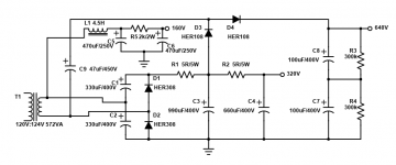
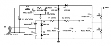
I added a schematic to an earlier post, Tony. The 160V, 320V, 640V supply. What do you think of it? 34
EDIT: I think 34 won't work, but this will?
BTW 4.5 Henry choke is there because I have some and they cost me 5$. Probably it can be left out, and the second cap could be a zener network instead, too.
One of them will, damn it!
EDIT: I think 34 won't work, but this will?
BTW 4.5 Henry choke is there because I have some and they cost me 5$. Probably it can be left out, and the second cap could be a zener network instead, too.
One of them will, damn it!
Attachments
Last edited:
- Home
- Amplifiers
- Tubes / Valves
- Lowering G2 voltage with power zener diodes