Connecting Pin 1 to Pin 8 can give some surprising results . . .
Most KT88 and most 6550 have a metal shell around the base.
Many KT88 and many 6550 connect that metal shell to Pin 1.
With a jumper from Pin 1 to Pin 8, the cathode voltage may be present on the KT88 metal shell, and the 6550 metal shell.
At your own risk . . . do that with Cathode Self Bias, or worse yet either Cathode Follower, or the use of Unity Coupled Output Transformers . . . Ouch!
As far as I know, the EL34 and 6CA7 are the only tube types that need to have Pin 1 connected to Pin 8.
Newbies beware.
Safety First!
Last edited:
To make my post # 41 more accurate:
I said:
"As far as I know, the EL34 and 6CA7 are the only tube types that need to have Pin 1 connected to Pin 8."
But what I should have said, is for the 6L6x, 6V6x, 5881, KT66, KT77, KT88, 6550, and similar type direct replacement audio output tubes in those families . . .
Only the EL34 and 6CA7 and similar type direct replacement audio output tubes need Pin 1 and Pin 8 connected.
With similar type direct replacement tubes, I am referring to the 6000, 7000, and 8000 series that are direct plug-in replacements.
Last edited:
Just a side note that any voltage rail derived from zener droppers will have a substantial level of ripple on it if the main B+ has significant ripple - even when there is filter cap on the G2 rail. This could be a hum issue for any PI or gain stage powered directly from the G2 rail, in which case a resistor in series with the zeners may be needed unless another RC is used to power other stages.
I added a schematic to an earlier post, Tony. The 160V, 320V, 640V supply. What do you think of it? 34
EDIT: I think 34 won't work, but this will?
BTW 4.5 Henry choke is there because I have some and they cost me 5$. Probably it can be left out, and the second cap could be a zener network instead, too.
One of them will, damn it!
i like #34 better...
the choke is a good idea too...i use that i my amp builds as well..
in this amp, i used two chokes, one for the main B+ and another choke for the G2 supply...
you can save on two parts, a resistor and a cap if you just stack up the caps for the 640v supply to the output of the 320v B+
Attachments
Last edited:
Connecting Pin 1 to Pin 8 can give some surprising results . . .
Most KT88 and most 6550 have a metal shell around the base.
Many KT88 and many 6550 connect that metal shell to Pin 1.
With a jumper from Pin 1 to Pin 8, the cathode voltage may be present on the KT88 metal shell, and the 6550 metal shell.
At your own risk . . . do that with Cathode Self Bias, or worse yet either Cathode Follower, or the use of Unity Coupled Output Transformers . . . Ouch!
As far as I know, the EL34 and 6CA7 are the only tube types that need to have Pin 1 connected to Pin 8.
Newbies beware.
Safety First!
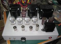
those black full metal types do have pin 1 connected to metal shells, it was common practice that time, i am not aware that kt88 that have metal bases have connections to pin 1, but i will look at it one more time...thanks for the heads up..
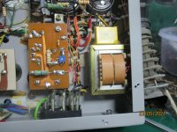
Hah, the pic is my little stunt from the mid '90s, nice to see it still getting some air timeOriginally tertrodes were designed to have g2 between 250 VDC and 300VDC. Schade mentions that ideally g2 should be 15 - 20V below the plate for optimum functioning. Attached document uses a string of 5.6V zeners due to the best temperature coefficient. I am using a single 30V zener in my current SE UL design resulting in a 20V difference between plate and g2. Works just as good.

Hah, “little stunt from the mid ‘90s”. And I took it for gospel 🤪 BTW, what diodes would you use now?Hah, the pic is my little stunt from the mid '90s, nice to see it still getting some air time
- Home
- Amplifiers
- Tubes / Valves
- Lowering G2 voltage with power zener diodes