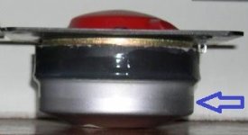
Attached is an American-German developed 2" mid-dome driver found in the ADS and Braun speakers. The unit in the photos was taken from ADS L980/2 speakers. As can be seen, the magnet is covered by a large metal cup on the back, blue arrow. I've acknowledged that the cup was installed there for forming a chamber or a closed enclosure to lowering the Fs of the unit.
In the L980/2, the high-pass crossover for that mid-dome is published at 450Hz. In addition, its bigger brother which utilizes the same midrange unit, the L1590/2 speakers, is published at 350Hz. While the smaller brother, the L880/2, is published at 550Hz, but it has no metal cup installed on the back of the magnet, as their bigger brothers, for lowering the Fs.
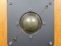
What's the trade-off of lowering the Fs, between having and not having the rear chamber on the back of the magnet? This question also applies to the large surround usage, in the picture of the front of the dome.
In the L980/2, the high-pass crossover for that mid-dome is published at 450Hz. In addition, its bigger brother which utilizes the same midrange unit, the L1590/2 speakers, is published at 350Hz. While the smaller brother, the L880/2, is published at 550Hz, but it has no metal cup installed on the back of the magnet, as their bigger brothers, for lowering the Fs.
What's the trade-off of lowering the Fs, between having and not having the rear chamber on the back of the magnet? This question also applies to the large surround usage, in the picture of the front of the dome.
Attachments

Last edited:
Open back has the lowest Fs and with tweeters, compression drivers it doesn't take a large back chamber to make it near enough an I.B..
To lower Fs you'll need to mod the suspension and/or add mass and/or compression horn load it (acoustic mass).
To lower Fs you'll need to mod the suspension and/or add mass and/or compression horn load it (acoustic mass).

Does it mean I misunderstood the concept that the rear chamber was used for creating a large volume closed box or something similar to IB? If so, what’s the real purpose, please?Open back has the lowest Fs and with tweeters, compression drivers it doesn't take a large back chamber to make it near enough an I.B..
In the case of closed chamber drivers (like typical dome tweeters etc), actually there is no Fs but Fc. You can lower Fc by enlarging or opening the chamber.
Fs is the free-air resonance of a driver without box loading, but the closed chamber of a driver is a box.
So modifying the fundamental resonance by enlarging the chamber needs to be treated like a closed box tuning.
Fs is the free-air resonance of a driver without box loading, but the closed chamber of a driver is a box.
So modifying the fundamental resonance by enlarging the chamber needs to be treated like a closed box tuning.
Last edited:
What do you intend for chamber?
A tweeter, a dome tweeter, will create a closed volume beneath the dome, and the magnet.
A bigger dome like a midrange will occupy more space and you would want to make a hole in the magnet pole so it communicates with the eventual cup, thus making a double chamber.
Some damping ( natural or synthetic felt) might be required...
First, I’d like to make sure that my understanding about that midrange dome with metal cup at the magnet is correct or not. If it’s not for the reason of lowering Fs, please, anyone educate me the right thing.
Electronically EQ-ing is not completely the same as enlarging the chamber, because below Fc, the efficiency drops like a rock and needs extra input power if one wants to play below that point and maybe the driver don't tolerate this well.
There are many threads and comments about small sealed box overheating because of force EQ-ing.
There are many threads and comments about small sealed box overheating because of force EQ-ing.
Last edited:
Frankly, I am now bewildered by the answers everyone tried to imply.
The reason that I thought the rear cup/chamber helps lowering the dome driver’s Fs was because the difference on high-pass crossover points, i.e., 350 and 450Hz for cup attached unit, and 550Hz without cup. That’s all.
The reason that I thought the rear cup/chamber helps lowering the dome driver’s Fs was because the difference on high-pass crossover points, i.e., 350 and 450Hz for cup attached unit, and 550Hz without cup. That’s all.
Aha, this resembles my idea that the rear chamber may help the drivers be able to go lower in frequency.needs extra input power if one wants to play below that point and maybe the driver don't tolerate this well.
It depends on what you are comparing it to. I think part of the confusion is the way your initial post is worded.
Adding a closed chamber to a driver with an open pole/basket/whatever will increase the Fs of the unit (or at best leave it unchanged), not decrease it. Same thing that happens when comparing the Fs of a woofer in free air to the Fc of that unit in a sealed box.
But on many midrange/tweeter domes, the lack of a rear cup means the enclosed volume is only above the magnet structure/under the dome, so that volume is smaller than that of one with a rear chamber. The smaller chamber makes for a comparatively higher Fs.
This is basically the same thing the others said, just worded differently.
the cup was installed there for forming a chamber or a closed enclosure to lowering the Fs of the unit
Adding a closed chamber to a driver with an open pole/basket/whatever will increase the Fs of the unit (or at best leave it unchanged), not decrease it. Same thing that happens when comparing the Fs of a woofer in free air to the Fc of that unit in a sealed box.
But on many midrange/tweeter domes, the lack of a rear cup means the enclosed volume is only above the magnet structure/under the dome, so that volume is smaller than that of one with a rear chamber. The smaller chamber makes for a comparatively higher Fs.
This is basically the same thing the others said, just worded differently.
Last edited:
I do not understand op why he wants to decrease Fs. Domes distort when driven too low.
Back chamber not only isolates dome from woofer, but rolles of dome making crossover easier, limits excursion thus increasing power handling.
Why would someone want to do exactly the opposite?
Back chamber not only isolates dome from woofer, but rolles of dome making crossover easier, limits excursion thus increasing power handling.
Why would someone want to do exactly the opposite?
As asked, yes.Does it mean I misunderstood the concept that the rear chamber was used for creating a large volume closed box or something similar to IB? If so, what’s the real purpose, please?
As others have noted, box size merely changes its damping quality factor (Qtc) and without measurement we don't know if it's large enough to qualify as making it a ~ I.B. loading.
For me (and presume the vast majority of us) it's to protect the driver from the LF driver's cab loading modulating its FR and potentially damaging it via over excursion and/or a long bass line 'sustain' overheating it and in rare instances, raise it's Qtc via box loading to further protect it by raising its effective Fs.
I see. I should have rephrased for more clarification, sorry.It depends on what you are comparing it to. I think part of the confusion is the way your initial post is worded.
There are two words that should have different meaning from each other.
I. Lowering Fs frequency
II. Lowering Fs level
I’m not sure if people will think of the impedance curve when talking about the Fs. But, those two words for me would be referred to things on the impedance graph.
So, let’s recognize again the understanding if it’s correct or not.
First, the ideal impedance response should have “Fs frequency” located as lowest as possible on the x-axis of the impedance graph, so that we could use the drivers as low frequency as possible. This explains the reason why those 2” mid-domes with cups installed on the back could be crossed at lower frequency's—350Hz (or 450Hz) versus 550Hz. Am I correct?
Finally, the desire impedance response should have the “Fs level” lowered. That’s mean decreasing the impedance level at the Fs frequency is preferred. The reason is the flatter the impedance curve, less impedance spike at the Fs frequency, the more it’s desired. Am I correct?
Last edited:
Using ferrofluid lowers the impedance peak. I may be mistaken but with tweeters it is called Fs but really is Fc and the rear volume is usually set for a Q= 1 FOR BEST POWER HANDLING.
Capitals for emphasis.
I take this to sometimes mean that a tweeter with a large rear volume needs a proper cross-over so that the tweeter isn't acting in its pistonic range. Although having said that I have often used such tweeters with first order crossovers with the caveat that when doing so it is usually in a Bi-Amp system where the bass to the tops is set at around 300Hz so the bass is well down at tweeter frequencies already.
A lot of older cone tweeters have a large space behind the diaphragm with simple first order crossovers [ a single cap in series] but these were always used well above their pistonic range.
I wish there was a simple explanation; one I could fully grasp; but it really is not simple.
If like old model Vifa tweeters the maker gives you a crossover diagram; that represents a minimum design criteria for that tweeter for the stated power handling; going lower or simpler changes that.
I've done some playing with modifying tweeters by adapting them to larger back volumes and extra fibre and damping and the changes are quite moderate and subtle, maybe a drop of 50 to 100 Hz is all
What ever, you don't want the Qtc to be low 0.56, under damped drivers have extremely poor power handling and it would be very easy to make a rear enclosure far too big, the optimum is; I guess; Q= 0.707
There is no lowering of driver Fs level, just a lowering of frequency response/Fc.I see. I should have rephrased for more clarification, sorry.
There are two words that should have different meaning from each other.
I. Lowering Fs frequency
II. Lowering Fs level
Fs is the resonant frequency of a driver and once enclosed it technically becomes its Fc, so in your bigger chamber case it's indeed lowering its Fc and vice versa, which in turn shifts the impedance peak lower to a lower acoustical impedance.
Correct, though measurements imply a 0.5 critically damped Qtc to quell any 'ringing' in its XO passband and one reason why they ideally need to be XO'd so high.Using ferrofluid lowers the impedance peak. I may be mistaken but with tweeters it is called Fs but really is Fc and the rear volume is usually set for a Q= 1 FOR BEST POWER HANDLING.
Adding a closed-box enclosure to a driver will not lower its resonance frequency. The cupped resonance frequency of the driver, Fc, will rise in proportion to Fc = Fs*sqrt(1+Vas/Vac), where Fs is the uncapped resonance frequency, Vas is the driver's equivalent acoustic volume representing the compliance of the suspension, and Vac is the air volume enclosed by the cup. For an uncupped situation, we can say that Vac = ∞, so fc = fs.As can be seen, the magnet is covered by a large metal cup on the back, blue arrow. I've acknowledged that the cup was installed there for forming a chamber or a closed enclosure to lowering the Fs of the unit.
It seems likely that the cup was filled with acoustic absorption materials of some type. It would have been intended to absorb any rearward radiation from the driver and minimize acoustic resonances in the rear chamber, which could have shown up in the driver's sound pressure response.
Are you quite sure that the L880/2 did not have a cup installed? The midrange driver needs to be isolated from the low-frequency high-amplitude pressure variations inside the enclosure that are produced by the movement of the woofer. It could be expected that, without a cup/rear chamber, the 2-inch midrange unit would probably end up being damaged.In the L980/2, the high-pass crossover for that mid-dome is published at 450Hz. In addition, its bigger brother which utilizes the same midrange unit, the L1590/2 speakers, is published at 350Hz. While the smaller brother, the L880/2, is published at 550Hz, but it has no metal cup installed on the back of the magnet, as their bigger brothers, for lowering the Fs.
Noting the abovementioned physics of the situation, adding the rear chamber to the midrange unit (installing a cup) will not lower the midrange's working resonance frequency Fc, but will instead increase it.What's the trade-off of lowering the Fs, between having and not having the rear chamber on the back of the magnet?
Although it's true that having a low Fs for a midrange driver is helpful, it needs to be kept in mind that, for a given size driver (e.g., our 2-inch midrange), lowering the driver's resonance frequency will produce a concomitant reduction in the sensitivity of the driver. That's just simply the Thiele–Small parameters at work.First, the ideal impedance response should have “Fs frequency” located as lowest as possible on the x-axis of the impedance graph, so that we could use the drivers as low frequency as possible.
When we have a 2-inch midrange with enclosure, we have a closed-box system, which produces a given resonance frequency, Fc, in the impedance curve.Finally, the desired impedance response should have the “Fs level” lowered.
Depending on the system parameters, i.e., the Qtc of the system response, we will get different acoustic responses from the 2-inch midrange at low frequencies above and below Fc.
For example, Qtc = 0.7071 will produce an SPL that is −3dB at Fc relative to the response in the passband. A Qtc = 0.5 will produce an SPL that is −6dB at Fc. If we design the system to have Qtc = 1, then the response will be 0dB at Fc, with a peak of about 1dB at 0.35 octaves above Fc.
@presscot imo in most cases for these smaller dome drivers the rear chamber is there for practical reasons making it possible to mount it in a speaker box sharing the same space with a larger driver that otherwise could damage the smaller one if there was no rear chamber protecting it from the much higher pressure caused by the larger driver, only some manufacturers and/or some of their better premium drivers get the fine tuning attention of the rear chamber for a best possible compromise given within its restraints, but mostly it's a big enough cup not affecting the Fs too much that gets slapped on and with some arbitrary amount of damping material added, and a quick fr and csd measurement, and if everything looks good they would call it a day.
Last edited:
- Home
- Loudspeakers
- Multi-Way
- Lowering Fs, trade-offs?