Yes, could be that plastic Lorlin/Alpha selector switch. They have silver plated contacts with low pressure that become unreliable after some years. Check the switch by using other inputs too. Check by repeated action of other input switching like any monitor or CD direct switches - they are notorious for bad or even broken contacts. When in doubt, test for connection quality using a resistance scale or the conductivity beeper on your DMM.
Assuming there is a balance control, don't forget that may effectively be in parallel with the volume control and so, also a suspect.
Assuming there is a balance control, don't forget that may effectively be in parallel with the volume control and so, also a suspect.
Last edited:
Shorted inputs of the volume pot, and it works... I bet now it's an easy task for you!
It should be before the volume pot... input selector?
An easy task for you 😀 You have it in front of you, I don't.
Volume control itself may be faulty.
Gajanan Phadte
It may well be.
Yes, could be that plastic Lorlin/Alpha selector switch. They have silver plated contacts with low pressure that become unreliable after some years. Check the switch by using other inputs too. Check by repeated action of other input switching like any monitor or CD direct switches - they are notorious for bad or even broken contacts. When in doubt, test for connection quality using a resistance scale or the conductivity beeper on your DMM.
If you only have a DVM then do basic contact and resistance checks as Ian suggests. It has to be something fairly straightforward causing this problem.
@CalamaoIf you only have a DVM then do basic contact and resistance checks as Ian suggests. It has to be something fairly straightforward causing this problem.
Never do a resistance check with an ohm-meter on a live device. Turn off or unplug and allow some time before measuring.
How to test this? 😕
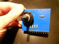
Checked for continuity between outputs (two of the three inner pins?) and inputs and it seems to work.
Tried to use some logic:
shorting inputs of the volume pot both channels work.
Volume pot is working.
Then the fault is before volume pot.
Input selector is working.
The signal travels as in the picture 1. Mmmm... how about the relay?
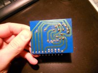
Tried to short inputs another time, before volume pot, as in the picture 2. After a noise like a little electrical discharge the working channel doesn't work anymore, but the faulty channel starts to work. Oh. Tried to short another time, both channel start to work. Ohh.
Switched off. Switched on. The faulty channel no longer work. Shorted another time, it works.
Should I replace the relay?
shorting inputs of the volume pot both channels work.
Volume pot is working.
Then the fault is before volume pot.
Input selector is working.
The signal travels as in the picture 1. Mmmm... how about the relay?
Tried to short inputs another time, before volume pot, as in the picture 2. After a noise like a little electrical discharge the working channel doesn't work anymore, but the faulty channel starts to work. Oh. Tried to short another time, both channel start to work. Ohh.
Switched off. Switched on. The faulty channel no longer work. Shorted another time, it works.
Should I replace the relay?
Attachments
Last edited:
Nice experimental work - Are you activating the relay when you short inputs? Otherwise it would seem that you are right. Not having a schematic, I couldn't be sure the device was a signal relay - that's unusual, presumably as a muting switch, in amplifiers of the period.
You can bridge the switched relay contacts in the bad channel with a piece of wire, preferably soldered so that it doesn't touch somewhere when the amplifier is powered, shorting out something that causes damage. Take care also that you don't short the 2 relay power connections which are spaced away from the switched ones, at one end. There may be a tiny diagram showing connections on the case. You can Google "signal relay" or the brand+part number for indications if in doubt.
It's likely the relay is obsolete so you will need to determine its supply voltage from the label or measure the voltage applied when it is energised. I'm guessing approx. 12V.
There will be many near equivalents but the pin spacing must be identical. Perhaps start with suppliers like RS and Farnell who have local outlets.
Possibily a tape-monitor relay? (as suggested here: http://ftbw.de/xp/amplifier-xp/oa-20-2.html )
Should I short NO1 and NO2? Checked for continuity between Com1-NC1 and between Com2-NC2 and everything is fine.
Relay is 47w/7, I've found a replacement on eBay ("BT47 Relay 24Vdc 2 Amp DPCO BT47W7 PCB Fujitsu", as usually eBay link don't work).
Should I short NO1 and NO2? Checked for continuity between Com1-NC1 and between Com2-NC2 and everything is fine.
Relay is 47w/7, I've found a replacement on eBay ("BT47 Relay 24Vdc 2 Amp DPCO BT47W7 PCB Fujitsu", as usually eBay link don't work).
Attachments

Last edited:
No, the idea was to bridge (or short) the NC1 to COM1 and NC2 to COM2 - assuming that the relay is actually in the NC (normally closed) position when the monitor switch is in the source position. Otherwise you simply bridge NO1 to COM1 etc. instead......Should I short NO1 and NO2?.....
This simply tests whether both sets of relay contacts are working properly, simultaneously, since that is where there appears to be a problem. I guess you realise the relay switches the amplifier input from the source to a recording device that has a replay signal so you can hear the recording instead of the source. If you don't need a tape monitor input or switch, remove the relay and just fit solid wire links to the NC-COM (see comment above) holes of both channels. No relay- no problem! 🙂
Last edited:
Great. Congratulations.
I guess this relay does not switch the tape, I think it is a muting relay.
Have you tried the various sources.
I see you can select CD or DISC or TUNER or TAPE IN.

I guess this relay does not switch the tape, I think it is a muting relay.
Have you tried the various sources.
I see you can select CD or DISC or TUNER or TAPE IN.
Have you tried the various sources.
Yes I did. Just ordered a proper replacement on eBay 🙂
More about the relay, from the ONIX OA20 designer:
http://www.diyaudio.com/forums/solid-state/31030-onix-oa-20-2-amplifier-parts-service.html
http://www.diyaudio.com/forums/solid-state/31030-onix-oa-20-2-amplifier-parts-service.html
Bridged relay... both channels now working.
Thank you VERY much to everyone.
That's great to hear. The power of the forum 😀
Onix OA20 bias setting
Amp works flawlessly now but I would like to adjust the bias, any clues about the proper setting?
Amp works flawlessly now but I would like to adjust the bias, any clues about the proper setting?
I wouldn't like to guess for a couple of reasons...
The correct bias depends on the type of configuration of the output stage. Is it an EF (emitter follower) or CFP (complementary feedback pair) ?
Also the "correct" bias according to what is best for the circuit may be to high for the heatsinking abilities of the design. (Commercial restraints)
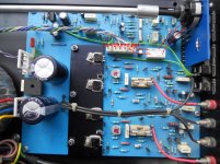
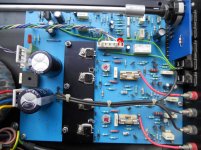
Do you see those four 0.22 ohms in your pictures. The red looking resistors (red, red, silver, silver code). If you measure the voltage across one of those (per channel) you can calculate the bias current from ohms law. See what both channels are running at for interest but don't alter anything. Around 100ma for an EF stage and 10 to 15ma for a CFP would be normal.
The correct bias depends on the type of configuration of the output stage. Is it an EF (emitter follower) or CFP (complementary feedback pair) ?
Also the "correct" bias according to what is best for the circuit may be to high for the heatsinking abilities of the design. (Commercial restraints)
Do you see those four 0.22 ohms in your pictures. The red looking resistors (red, red, silver, silver code). If you measure the voltage across one of those (per channel) you can calculate the bias current from ohms law. See what both channels are running at for interest but don't alter anything. Around 100ma for an EF stage and 10 to 15ma for a CFP would be normal.
- Status
- Not open for further replies.
- Home
- Amplifiers
- Solid State
- Low volume channel