Just found an Onix OA20 amp, left channel has a very low volume. Tested transistors and they mesure fine; tested dc offset: 20mv from both channell; maybe a faulty pot? Tried with some spray but it still crackles just on left channell and no higher volume from it. Any help very welcomed. Thank you.
One diagnoses an amp with a DC DVM to see if all the voltages are plausible considering the way parts work. If that dosn't work one injects some R&R music and looks for the beats with the AC scale of a VOM, VTVM, or scope. Block one probe with a .047 600 v capacitor on a VOM or VTVM, they will read Dc voltages on the AC scale. DVM is mostly not useful on music, they average over about 4 seconds and tend to produce random numbers on frequencies other than that of the power line.
Agreed, you inject a defined signal and measure the result progressively back through the signal chain with an instrument that responds to that signal. An oscillator with an oscilloscope is the ideal combination. These can even be free PC software implementations.
If you have no tools to work with, a gadget like the amplifier section of a radio or even the other channel of the amplifier can be used independently as a tracer if you have nothing else to work with. Using a film capacitor in line (say 100nF), you then probe the preceding sections of the preamp back from the actual power amplifier input to the signal input socket and compare channels by ear to locate where the signal gets lost or is substantially different at least. In this case I'd cut to the chase and start around the volume control/balance controls if applicable. Obviously, keep the signal level low enough not to do damage when injecting signal after the volume control.
However, there are often switching problems as well as pots that wear out. Go through them all and check that each is working correctly and that any headphone socket isn't the cause of it. This thread tells us that even a hand drawn schematic has been lost and unavailable.
http://www.diyaudio.com/forums/parts/19033-onix-soap-needs-re-cap-3.html
What is it with UK design/manufacture of audio electronics that everyone including designers, builders and service agencies lose critical documents and no service agencies have ever had proper documentation either? One wonders what service people really worked with when such products hit the workbench. A complete industry shambles or just exaggeration and guesswork?
As is usual, E-bay errors out and says listings over 90 days old are invalid. Let's see, that link was 2 hours old?
"PC scopes" which are software that uses the sound card in the PC, do not have a "ground" isolated from the wall plug ground. these are not safe to use on defective equipment, especially by newbies. If you run into an amp that has a "flying ground" a grounded instrument would be totally useless.
If this device was a portable instrument in a double insulated plastic case, then your main worry is that half of everything electronic for sale on e-bay is complete trash, IMHO. Look for the CE, UL, CSA, or VDE rating, although these logos can be counterfeited, too.
Last edited:
Sorry for the invalid link... Actually I never used an oscilloscope so I even don't know if this one has the right specs for testing an amplifier. I've read very good reviews tough.
Pocket-Sized Digital Oscilloscope DSO Nano DSO201
DSO Nano DSO201 Pocket-Sized Digital Oscilloscope Review - ToolBoom Online Store
Pocket-Sized Digital Oscilloscope DSO Nano DSO201
DSO Nano DSO201 Pocket-Sized Digital Oscilloscope Review - ToolBoom Online Store
The 1 mhz sample rate should be mostly adequate, the 10 mv/div gain should help you debug preamp circuits, the 80 v maximum deflection is only good enough for first projects. My PV-1.3K amp swings 170 v.
It does apparently allow trigger sensitivity and type to be selected, although how stable the trigger is on a noisy signal is not something tested. Teks were stable, Televideos and heathkits were not stable on a noisy signal.
Whether the probe ground is connected to the safety ground of the wall plug when the USB cable is plugged in is not a specification that is listed that I can see.
Good luck. Incredibly cheap.
Thank you very much Indianajo.
Should I buy an oscillator too or could I use the built-in square wave signal generator? I will look for some tutorial about troubleshooting the amp using the oscilloscope.
Should I buy an oscillator too or could I use the built-in square wave signal generator? I will look for some tutorial about troubleshooting the amp using the oscilloscope.
"Frequency Generator
The signal generator will output a square wave that can be used for test purposes (refer to the section on “DSO Nano Operation” for information on where the test signal output connector is located on your Nano). Output swing is from ground to the internal DSO lithium battery level. The output signal will peak (logic high level) at just above 3V for a near empty battery to 4.3V for a fully charged or charging battery. Peak-to-peak voltage (Vpp) may rise slightly above battery level due to a small undershoot (falling edge) and overshoot (rising edge) on the output square wave. Output level amplitude can not be altered.
Signal generator output frequency and duty cycle can be controlled as follows:
Output frequency can be set to three digits of precision in the range from 10Hz to 1MHz using menu FR and sub option “Freq Out”. Press the B key to cycle between 1, 2 and 3 digits of precision. Press left or right to alter the highlighted digit.
Duty cycle (pulse width modulation) can be set with sub option “Freq Duty” in steps of 1% (using left or right keys) from fully off to fully on. Press the B key to reset duty cycle back to the default 50%."
BenF V3 firmware users guide for Seeed Studio DSO Nano V1 and V2
Version 2 has a 3.5 mm audio compatible signal generator output: any better?
DSO Nano [v2] official leak
Last edited:
Hi Calamaro
Take great care with DSO Nano scopes on amplifier voltages, whatever the input peak rating of 80V implies. It doesn't have proper input attenuators like test oscilloscopes do so there is always a risk with bad earthing, that you can damage the scope. At the least, you would also need to buy and use a x10 probe as insurance. Obviously that reduces your input voltage to only 10% of the real voltage so you must scale the reading.
The internal generator is a squarewave type and this is bad for audio amplifiers unless they are being torture tested under controlled conditions. The waveform should be sinusoidal. There is no reason you can't couple a tone output from your PC sound card if you can establish that the amplifier signal input ground is at the same potential as the PC's output ground. You can also buy CDs of test tones at varying levels and pitches, which make advanced testing quite simple. Remember to couple inputs with a high voltage isolating capacitance as suggested earlier. Try generating a 400 Hz tone of O.1V peak-peak, which is easily audible.
Still, I would first use an another amplifier to listen with rather than go through spending large sums of money on test equipment that you still need to learn about before you get sensible measurements. Hearing is understanding simply too and when you are looking at simple go/ no-go testing, a scope may be overkill unless you need to make more precise measurements.
Hi Ian, it's a little cheap device (40 euros delivered) so if can help to find the fault and to learn something new I would be really happy to spend this little sum of money. Though I will try your way first.
Last edited:
Agreed, you inject a defined signal and measure the result progressively back through the signal chain with an instrument that responds to that signal.
Problem is that there is no service manual available so how to trace the signal path?
Problem is that there is no service manual available so how to trace the signal path?
Experience I'm afraid.
If the DC conditions are OK then the gain of any conventional amp is set by just two or three components (the feedback network). If you suspect the volume pot or a simple input problem then just short the L and R inputs of the two channels on the PCB to see if you get equal output.
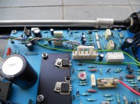
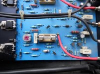
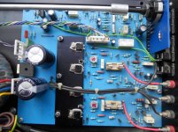
If you post a detailed and clear close up showing the internals we might be able to help more.
Pics.
Hi Mooley, we have some pictures.
How about short the L&R inputs? Just connect them before the pot?
I also checked pot resistance and both channel have the same value.
Hi Mooley, we have some pictures.
How about short the L&R inputs? Just connect them before the pot?
I also checked pot resistance and both channel have the same value.
Attachments
Last edited:
Before your scope gets there, I'd reseat that white connector without thinking too hard. The connector in my WP25 soldering iron quits frequently, and that is at 120 vAC. That is how I got it, I found it laying on the ground at the ATM at the bank. A little scraping and bending with a pick on the socket, I'm working again.
Thanks for the pics. Hmmm... I still can't decipher it unfortunately. I was actually meaning to short the inputs of the power amps together so that would be the equivalent of shorting the wipers on the volume control together. Its worth trying but the VC is still remote from the amp inputs on the board, so anything physical, or if there were a component en route that were faulty would still be missed.
I see two electrolytics near the inputs of each power amp (near the speaker sockets). One could be an input coupling cap and the other the feedback return cap. Might be worth a look at those although I would expect the amp to be bass light if one had failed... but you never know.
I see two electrolytics near the inputs of each power amp (near the speaker sockets). One could be an input coupling cap and the other the feedback return cap. Might be worth a look at those although I would expect the amp to be bass light if one had failed... but you never know.
I was actually meaning to short the inputs of the power amps together so that would be the equivalent of shorting the wipers on the volume control together.
Shorted inputs of the volume pot, and it works... I bet now it's an easy task for you!
It should be before the volume pot... input selector?
Last edited:
- Status
- Not open for further replies.
- Home
- Amplifiers
- Solid State
- Low volume channel