HI all,
I am new to tubes.
I have been doing some simple tube preamp circuits using a 24v SPU.
They sound good to my ears...good enough to build the preamp to replace the current one. Clear, open, good imaging and dynamics. However I know that Tubes run at higher voltages.
My question is-
If I am getting good sound and gain off of 24V for B+...would it be a major improvement to use higher voltages?(I need low gain).
Would 48V B+ be an improvement? Or do I have to go 100+ V.
I've had ARC Flash training and such...but I would prefer lower Voltage and amperage. Pre-amps are kinda a relief vs. power amps in terms of amperage. I know It takes way less than an amp to be lethal... so the same safety practices for any electrical work...but less chance of arcing with lower amperage.
Being married with 2 young boys puts electrical Volts and Amperage measurements into a different measurement scale.
Thanks all
Roger
For a genuine valve preamp you need 200V or more. 24V or 48V will give you an FX box. Some people like these.
I would try the ECC88 and its cousins. They are designed for plate voltage of around 90V.
The smaller the signal, the more linear low voltage tubes will be.
The smaller the signal, the more linear low voltage tubes will be.
One way of improving the linearity with a low HT supply is to use a constant current source as an anode load.
CCS's and gyrator plate loads do absolute wonders to tube gain stage linearity, but they need MORE voltage headroom rather than less.
Choke is the best plate load for low voltages.
Which tubes are you using at the moment?
Choke is the best plate load for low voltages.
Which tubes are you using at the moment?
'...constant current sources... ...permit a valve to achieve low distortion from a low HT supply.' - Morgan Jones, Valve Amplifiers 3rd. Ed. P135
Thanks for the replies,
And for your suggestions
I am using a single 6FQ7 and a 7n7 for the other...with the 7N7 being more detailed but not as much bass.
I did a Jfet preamp as well as a Mosfet and OPA-2134 opamp pre amps.
So far these tube preamps sound the most accurate...more so than my SS Marantz.
So if this is an FX Box...then so be it. It is more accurate than a SS Marantz that went for $350 in 1977.
I have had many failures in amp building...and have no problem saying it s-cks and keeping the commercial model. I only keep what sounds accurate to me...which doesn't happen often. So something is going right with this one so far. 🙂 I guess more voltage may be needed.
Would lower resistor values on the resistor from the supply to the plate and from cathode to ground allowing more current be better?
Would the constant current source be best achieved via solid state or a tube?
Sorry if I sound naive...still learning...and will until death.
Would the constant current source be best achieved via solid state or a tube?
Sorry if I sound naive...still learning...and will until death.
Last edited:
I'd recommend solid state, it's easier to implement, costs less voltage. You could try the Supertex LR8 HV regulator for currents <~15mA or Ixys 10M45 for higher currents, or you can build a BJT cascode with MJE340 transistor.
Why not download LTSpice and try some simulations, they'll give you a bit better idea how tubes behave under different conditions. Buy the Morgan Jones book.
Here's a link on how to build SS CCSs:- diytube.com • View topic - EZ Sink: Depletion-mode MOSFETs and the LM334
Why not download LTSpice and try some simulations, they'll give you a bit better idea how tubes behave under different conditions. Buy the Morgan Jones book.
Here's a link on how to build SS CCSs:- diytube.com • View topic - EZ Sink: Depletion-mode MOSFETs and the LM334
rcollege,
There's really but 1 tube suited to preamp service in a LOW B+ voltage regime. It's the 6GM8/ECC86.
You set up battery biased (-3 V.), CCS loaded, cathode followers, which are "unity" gain. The 10M45S integrated circuit is a "good enough" CCS for this job. A 50 V. B+ rail should be adequate.
There's really but 1 tube suited to preamp service in a LOW B+ voltage regime. It's the 6GM8/ECC86.
You set up battery biased (-3 V.), CCS loaded, cathode followers, which are "unity" gain. The 10M45S integrated circuit is a "good enough" CCS for this job. A 50 V. B+ rail should be adequate.
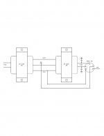
A nice preamp power supply can be created using back to back transformers. This allows cheap salvaged transformers to generate a nice 240V B+ which is intrinsically fairly safe because it is current limiting.
Shoog
Shoog
Shoog -
I was just thinking of that this morning - using up some 240v:12v toroids I have. I've done that before and it works just fine.
Can you explain how it is "current limiting"?
One more thing - how do you implement mains filtering with a back to back setup? I remember Thorsten using some combination of capacitors and inductors between the two transformers. Could you point me to some circuits for mains filtering, or post a diagram?
Best, Andy
Shoog -
I was just thinking of that this morning - using up some 240v:12v toroids I have. I've done that before and it works just fine.
Can you explain how it is "current limiting"?
One more thing - how do you implement mains filtering with a back to back setup? I remember Thorsten using some combination of capacitors and inductors between the two transformers. Could you point me to some circuits for mains filtering, or post a diagram?
Best, Andy
Its current limiting because each transformer multiplies its regulation together when overloaded, hence voltage tends to droop significantly if shorted.
EI's work best because they they act as two line hash chokes whereas Toroidals tend to pass line hash easily. I never bother with anything more than standard line filter or a suitably rated capacitor across the mains.
One thing to remember is that the two secondaries which are back to backed cannot be used to create a voltage step up otherwise they saturate the second transformer, ie 240:6||6:240
The issue to be concerned about is the mains side of the arrangement - which certainly can kill easily, and you have that in any circuit you build.
Hi voltage transformers suitable for preamps are hard to get at reasonable cost where I live, so I have used back to back transformers in almost all of my pre-amp circuits and for the front end of many of my power amps. Never had an issue if they are spec'd adequately.
PS- ECC86's are now very expensive since Broskie published a version of his Aikido amp using them. They sound every bit as good as a higher voltage tube in this particular circuit and they run off a B+ of 24V.
Shoog
Last edited:
One thing to remember is that the two secondaries which are back to backed cannot be used to create a voltage step up otherwise they saturate the second transformer, ie 240:6||6:240
Shoog
Are you saying that you CAN'T use 240:6||6:240? If so why, if the current is within the transformer's specifications?
Don't quite know what you're saying here! Are you talking about how to connect a transformer with two secondaries, like 0-6, 0-6? If so are you suggesting to connect the secondaries in series or parallel or what?
I've used 240:0-6,0-6 > 0-6,0-6:240 this way connecting the lower voltage secondaries in series. I've even run a 12v rectifier off the 0-6,0-6 series connection of the first transformer as well. All this is assuming the transformers are well within current spec.
Andy
Last edited:
Are you saying that you CAN'T use 240:6||6:240? If so why, if the current is within the transformer's specifications?
Don't quite know what you're saying here!
Andy
Sorry, not clear enough
240:6||6:240 is OK
240:8||6:240 is not OK.
Shoog
I've been running a 6DJ8 Phono Stage for years now using Back to Back RS 12v 3A CT Transformers...After the 6X5G and Choke they give 140v B+....The Pre sounds Very Good, and the RS's never get Hot...
I've been running a 6DJ8 Phono Stage for years now using Back to Back RS 12v 3A CT Transformers...After the 6X5G and Choke they give 140v B+....The Pre sounds Very Good, and the RS's never get Hot...
How do you run transformers back to back?
How do you wire them?
Sorry don't know much about the transformers.
Last edited:
yep.Thanks Sled108,
I have an isolation transformer...would that work as a supply?
Shoog
- Status
- Not open for further replies.
- Home
- Amplifiers
- Tubes / Valves
- Low voltage vs. High Voltage Preamp.