Hi Ripson,
Not disagreeing with you, just wondering the reasons you sight against voltage stabilization. Also I' m not sure if you actually mean voltage regulation (i.e. with feedback) or literally just plain zenor type stabilization.
Thanks
Not disagreeing with you, just wondering the reasons you sight against voltage stabilization. Also I' m not sure if you actually mean voltage regulation (i.e. with feedback) or literally just plain zenor type stabilization.
Thanks
I meant voltage regulator, which responds to the back EMF from the voice coil and attempt to correct this "error" by injecting current, which unfortunately introduces noise, and distortion.
Hi ripson
Just popped my head back in and noticed your progress with the Rod Coleman CCS and your field coils.
I would be very interested to know how it might compare to the CCS I got with my Sonidos.
I have interest in exploring more field coil ideas and options.
I have collected materials and hope to build some of my own field coil motors when I have my machinery up and running again.
I want to try them on some Lowther drivers I have.
Can you share any details on what parameters where considered the most important when designing the Coleman CCS? Perhaps some pictures of how you constructed it?
interesting, what is the voltage and current variation observed consider 12ohm Field coil resistance and you are applying 12V on the field coil.
If the back emf as per your above sim take extreme case of 20V on the speaker at 2KHz as I might like to play relatively louder.
What are the voltage and current sags observed on the field coil?
If the back emf as per your above sim take extreme case of 20V on the speaker at 2KHz as I might like to play relatively louder.
What are the voltage and current sags observed on the field coil?
so do you mean to say something like CLC type just with transformer?And the worst thing you can do is to power the FC with a voltage stabilized PSU!
Also have you tried using SMPS?
Now what kind of sags observed with tube rectifier many FC owner vouch for tube rectifiers at higher voltage?
For the details, I recommend contacting @Rod Coleman . He is the best person to provide any specifics you might need.


Attachments

Thanks @ripson ! - Yes, the Field Coil supply is a stable current-out regulator.For the details, I recommend contacting @Rod Coleman . He is the best person to provide any specifics you might need
Why use a pure current drive to a field coil?
- The B-Field (real magnetic field) is controlled by current - so stable current means stable magnetic field.
- As noted previously, the Coil ESR (coil resistance) comes from the copper of the coil, so it increases with temperature. With the high current in the coil, self-heating makes this is difficult to ignore. A voltage regulator can't tell what's going on, and so the current, and magnetic field droops as it warms up.
- Voice-coil back-EMF from the music-signal will impose some signal-voltage across the field-coil. This should be left undisturbed.
My field coil driver does not sense across the coil at all, and the current is stable, with or without music playing.
But a voltage regulator reacts to signal voltages the same way it does to DC voltage shifts... it thinks there's an error, and throws current at it, to cancel it out. This is undesirable in itself, but consider also that the voltage regulator is not high fidelity - it will add distortion and noise to the "error" current it sends in.
My regulator is a DIY kit that is a special version of the one used to heat the filaments of DHTs (300B triodes, etc). It's been used for > 14 years now by those on diyAudio and beyond, and has a record for high reliability. It's adjustable, so you can easily find the current for best sound.
The Field Coil is a special version, because a current regulator can't simply be loaded with an inductance - it will oscillate for sure.
So the field coil version is designed to frequency-compensate for the inductive load, and can now drive coils all the way up to 10H (or even more !)
Last edited:
Hi Rod coleman nice to see you on the thread. I have a question, now consider the output voltage is about 17V and as I have simulated a standard shunt regulator where I want to drive a 15 inch Field coil driver at full throttle but I see a current variation of about 0.6Amp but at higher frequencies the variation of current through field coil is about 0.5Amp when the CCS of the shunt is about close to 1.8Amp.
Now how much sag is observed in the above case with your regulator where 17V of the Field coil voltage with field coil resistance being 12ohm? at 80V on speaker with 5000Hz of speaker operating frequency
How much at 80V on the speaker with 20Hz as well. Wanted to understand how stiffer is your regulator?
Attachments
Hi @rhythmsandy .but I see a current variation of about 0.6Amp but at higher frequencies the variation of current through field coil is about 0.5Amp
The current you're seeing in the field coil is a direct result of the shunt regulator action. In signal terms, this is a voltage regulator - so the circulating current is a consequence of feedback sensed at the coil terminals by the FET source.
If you replace this regulator with the RC-V9 Field Coil regulator, the regulator signal-current is near to zero.
I wouldn't expect the coupling coefficient between the field coil and the voice coil to be very close to 1 though, anyway. How are they wound in relation to each other?
I've had a CCS on my field coils for a while now. For one I did measure the signal in the voice coil coupling into the field coil and wanted to break the fc supply current loop by introducing a high impedance node. And as was mentioned a couple of times already B depends on I. The field coil does heat up so coil DCR goes up. With a fixed voltage this means I drops -> B drops. With the CCS B is stable and the speaker's sound doesn't change during warm up. It sounds (and measures...) the same right after turning it on and an hour or two later.
Rant: Positioning probably doesn't matter much in case of a field coil supply CCS but NOT putting a high impedance node like a CCS close to it's load gives me a headache.
Rant: Positioning probably doesn't matter much in case of a field coil supply CCS but NOT putting a high impedance node like a CCS close to it's load gives me a headache.
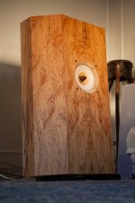
Power he field coil with a stiff voltage source.I am in possession of a nice pair of modern full range field coil speakers.
I've been advised to build a passive power supply for the field coils, about 10V supply. Despite that I am really impressed how efficiently 100Hz ripple is suppressed by these passive PSUs, there are two things that are missing in such a supply, current regulation and current stabilisation.
The field coil has the inductance of 200mH, Rdc=11 Ohm at 20 °C, however it might rise to 13.6 Ohm when the copper wire reaches 70 °C.
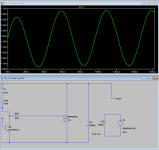
According to Faraday's law the magnetic flux is proportional (before saturation) to the current flowing through the coil. And if we apply the constant voltage, and when the Rdc rises the current will slowly drop. So at first I thought about the traditional CCS, so constant current, constant magnetic flux, but I didn't think about the fact that the voice coil electromagnetic field will induce the current in the field coil, so CCS would instantly countreact to the current change and would have a negative impact on the sound.
So I added an opamp integrator and a low pass filter with a very low cut off frequency that slows down the process of adjusting the field coil current of a few seconds.
I know it's not rocket science, a capacitance multiplier, it's actually quite simple, but still it has a low output impedance, no instant feedback, flat frequency response to the EMF from the voice coil, I compared it to the dedicated passive PSU and it's almost identical plus regulation and stabilisation. I know that using these two stages is an overkill, the second would do the job but I like it that way. The Sziklai pair would have a smaller voltage drop across the power BJT (so smaller power dissipation), but I was worried about the oscillation so I used Darlington.
However, maybe I am missing something here, I am not doing electronics on a daily basis so maybe more experienced colleagues could help me find some weak spots, some improvements before I start designing PCB.
I have added LTSpice simulation for anyone who would like to use it as it is or do some changes.
That doesn't make sense. Read my message above. Or Rod's. A voltage source will lead to a change in B when the field coil temperature changes. Which it will.
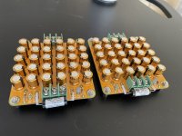
It is just a paralel field of 30 pcs 100uF capacitors with very low esr on each channel, with a 0,1uf bypass
It is intended to be like a small scale spot welding module, capable of delivering very fast small currents
It is intended to be like a small scale spot welding module, capable of delivering very fast small currents
Last edited:
No. A CCS is totally different. A CCS for a field coil supply is not as critical as in other positions and a 2540 cascode is good enough. The most expensive part will be the heat sink.
@bogdanrosca "capable of delivering very fast small currents" doesn't hurt, but for a field coil supply this is not needed. You need a supply that keeps the B field (which is depending on the current through the coil) constant.
For the 0.1uF bypass: I don't think it will do anything in that capacitor bank, but if it was to have an effect for HF decoupling you should try to mount it with leass lead length to not sabotage that. This is where SMD parts shine.
For the 0.1uF bypass: I don't think it will do anything in that capacitor bank, but if it was to have an effect for HF decoupling you should try to mount it with leass lead length to not sabotage that. This is where SMD parts shine.
- Home
- Loudspeakers
- Full Range
- Low voltage field coil PSU - "slow CCS"