I am in possession of a nice pair of modern full range field coil speakers.
I've been advised to build a passive power supply for the field coils, about 10V supply. Despite that I am really impressed how efficiently 100Hz ripple is suppressed by these passive PSUs, there are two things that are missing in such a supply, current regulation and current stabilisation.
The field coil has the inductance of 200mH, Rdc=11 Ohm at 20 °C, however it might rise to 13.6 Ohm when the copper wire reaches 70 °C.
According to Faraday's law the magnetic flux is proportional (before saturation) to the current flowing through the coil. And if we apply the constant voltage, and when the Rdc rises the current will slowly drop. So at first I thought about the traditional CCS, so constant current, constant magnetic flux, but I didn't think about the fact that the voice coil electromagnetic field will induce the current in the field coil, so CCS would instantly countreact to the current change and would have a negative impact on the sound.
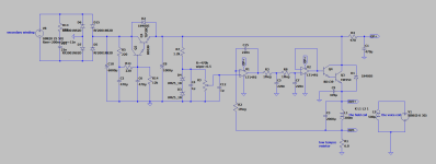
So I added an opamp integrator and a low pass filter with a very low cut off frequency that slows down the process of adjusting the field coil current of a few seconds.
I know it's not rocket science, a capacitance multiplier, it's actually quite simple, but still it has a low output impedance, no instant feedback, flat frequency response to the EMF from the voice coil, I compared it to the dedicated passive PSU and it's almost identical plus regulation and stabilisation. I know that using these two stages is an overkill, the second would do the job but I like it that way. The Sziklai pair would have a smaller voltage drop across the power BJT (so smaller power dissipation), but I was worried about the oscillation so I used Darlington.
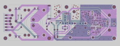
However, maybe I am missing something here, I am not doing electronics on a daily basis so maybe more experienced colleagues could help me find some weak spots, some improvements before I start designing PCB.
I have added LTSpice simulation for anyone who would like to use it as it is or do some changes.
I've been advised to build a passive power supply for the field coils, about 10V supply. Despite that I am really impressed how efficiently 100Hz ripple is suppressed by these passive PSUs, there are two things that are missing in such a supply, current regulation and current stabilisation.
The field coil has the inductance of 200mH, Rdc=11 Ohm at 20 °C, however it might rise to 13.6 Ohm when the copper wire reaches 70 °C.
According to Faraday's law the magnetic flux is proportional (before saturation) to the current flowing through the coil. And if we apply the constant voltage, and when the Rdc rises the current will slowly drop. So at first I thought about the traditional CCS, so constant current, constant magnetic flux, but I didn't think about the fact that the voice coil electromagnetic field will induce the current in the field coil, so CCS would instantly countreact to the current change and would have a negative impact on the sound.
So I added an opamp integrator and a low pass filter with a very low cut off frequency that slows down the process of adjusting the field coil current of a few seconds.
I know it's not rocket science, a capacitance multiplier, it's actually quite simple, but still it has a low output impedance, no instant feedback, flat frequency response to the EMF from the voice coil, I compared it to the dedicated passive PSU and it's almost identical plus regulation and stabilisation. I know that using these two stages is an overkill, the second would do the job but I like it that way. The Sziklai pair would have a smaller voltage drop across the power BJT (so smaller power dissipation), but I was worried about the oscillation so I used Darlington.
However, maybe I am missing something here, I am not doing electronics on a daily basis so maybe more experienced colleagues could help me find some weak spots, some improvements before I start designing PCB.
I have added LTSpice simulation for anyone who would like to use it as it is or do some changes.
Attachments


I do not want to discuss here the differences between the permanent magnet vs FC sound wise, but having controlled magnetic flux allows you to control the speaker's T/S params and find a required sweet spot which you can't do with a permanent magnet. Cheers 🙂
So at first I thought about the traditional CCS, so constant current, constant magnetic flux, but I didn't think about the fact that the voice coil electromagnetic field will induce the current in the field coil, so CCS would instantly countreact to the current change and would have a negative impact on the sound.
I've never been any good at electromagnetics, but isn't it an advantage when the current through the field coil stays constant no matter what voltage the varying magnetic field of the voice coil may induce in it?
This was also my thought, to make a fast setting CCS, but then I read this:
https://theaudiofeast.com/field-coil-psu
https://theaudiofeast.com/field-coil-psu
That link doesn't make much sense to me. They are apparently worried about the magnetic coupling between the voice coil and the field coil and the field coil acting as a shorted secondary winding for the voice coil, but if that is an issue, it is an issue no matter whether the voltage across the field coil is kept constant with feedback or with a big capacitor. A current source would be the ideal solution then.
A big cap will keep the a constant voltgage across the FC, CCS will start manipulating the voltage to keep the current constant compensating the voltage induced in the FC, I would say that is a big difference... well I hope that I am on the right path to having the advantages of a passive PS with the ability to slowly adjust the constant current. Time will tell 🙂
well... yes, and one thing is the "static" interaction between the coils, and another thing is that when the voice coil moves in a magnetic field, it causes back EMF... to be honest, I'm a bit lost with this.
What I did, I gathered experience/feedback from people who make FC speakers or experimented with a power supply for FC. Everyone says: simple is best, use passive power supply, no regulation, no feedback. Instead, I designed something that looks complicated but is actually simple. The feedback cutoff is below 1Hz, it won't affect the audio frequency at all.
I compared the passive one in LTSpice dedicated to these drivers with mine, it behaves the same as the passive one (actually a little better) + extra there is a slow current setting to a constant level.
Another thing... I have a current source amplifier that works amazingly with permanent magnet speakers. How will it work with FC Speakers... can't wait to check it out 🙂
Not sure what modern field coils you’ve got.
Mine are a pair of Sonido SWR250FC with 16ohm voice coils.
I use Istvans CCS power supply. He shared a schematic with me in case I wanted to build my own.
I have NO electrical engineering or circuit design experience…so I defaulted to Zen Mod for an opinion and he gave it approval.
I use my F2J monoblock clones to drive them. They are a perfect match for the Sonido.
Thank you for your comment Chromenuts. I have drivers from Zsolt Lajcsak, also a Hungarian guy 🙂 I have also F2J clone.
Zen Mod is my hero and I always could count on his knowledge and help.
It would be awesome to have two PSUs and compare these two different approaches one by one, however you are in States and I am - currently - in Italy.
Out of curiosity I have done some simulations of CCS by Papa recipe connected to my FC, 11-12 Ohm (when at 20 C degrees) and 200mH.

The current swing on the FC is about 2.7mApp at 25Hz:

and the voltage across the FC is:

However at 10kHz:

and voltage is totally crazy:

not well controlled IMO
Sadly I have nothing to say that can lead to any interesting conclusion :/
Zen Mod is my hero and I always could count on his knowledge and help.
It would be awesome to have two PSUs and compare these two different approaches one by one, however you are in States and I am - currently - in Italy.
Out of curiosity I have done some simulations of CCS by Papa recipe connected to my FC, 11-12 Ohm (when at 20 C degrees) and 200mH.
The current swing on the FC is about 2.7mApp at 25Hz:
and the voltage across the FC is:
However at 10kHz:
and voltage is totally crazy:
not well controlled IMO
Sadly I have nothing to say that can lead to any interesting conclusion :/
Last edited:
I did a simple test with "ideal CCS".

To keep constant current and surppress the 60mApp induced in the FC (in the above example) the voltage across the FC would need to swing like that:

at 10kHz, with very low output impedance.
These are very difficult conditions to met for CCS I would say. Someone more experienced would have a better understanding than myself.
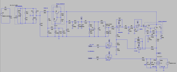
BTW I did a small mistake in Mr. Pass CCS, it should be like that:

To keep constant current and surppress the 60mApp induced in the FC (in the above example) the voltage across the FC would need to swing like that:
at 10kHz, with very low output impedance.
These are very difficult conditions to met for CCS I would say. Someone more experienced would have a better understanding than myself.
BTW I did a small mistake in Mr. Pass CCS, it should be like that:
Shouldn't a flyback diode also be included in the circuit ?
https://www.electronicshub.org/flyback-diode-or-freewheeling-diode/
https://www.electronicshub.org/flyback-diode-or-freewheeling-diode/
a capacitor in parallel with L1? It would keep a constant (depending on the capacitance) voltage across L1, fast setting CCS would not be working then.What happens if you place a capacitor in parallel after L1 ?
A diode like in the relay circuits that shorts the spike voltage and protects the transistor? I haven't seen anything like that in the simulation, changes are slow and there were no voltage spikes.Shouldn't a flyback diode also be included in the circuit ?
https://www.electronicshub.org/flyback-diode-or-freewheeling-diode/
so what is the conclusion?
consider if we get 40ma of variation across the Field Coil at 10KHz and 40microV of voltage variation on the voltage across Field coil and across the speaker terminal voltage swing is +/-5V as per above inputs. Is that good enough?
consider if we get 40ma of variation across the Field Coil at 10KHz and 40microV of voltage variation on the voltage across Field coil and across the speaker terminal voltage swing is +/-5V as per above inputs. Is that good enough?
Perhaps that advice is to try and eliminate something else's "character" getting into the sound that results. Make it as "dumb" (active feedback wise...) as possible. How about an empirical approach, where you drive the VC and "listen" to the FC with different cap values across it?Everyone says: simple is best, use passive power supply, no regulation, no feedback.
I had a chat with Rod Coleman about using his CCS, which is usually for DHT filaments, to power a low voltage field coil. He asked about my FC parameters and suggested a few tweaks for frequency compensation, avoiding phase shifts, and oscillations. Rod sent me his V9 kit, and after hooking it up and setting the right current, I noticed a nice bump in sound quality.
So, I built another one and sent it to Zsolt, a friend who designed these drivers, and he noticed the same improvements: better soundstage, tighter bass, and more natural voices.
In the end, I got a CCS that’s been professionally tuned, and I couldn’t be happier 🙂
So, I built another one and sent it to Zsolt, a friend who designed these drivers, and he noticed the same improvements: better soundstage, tighter bass, and more natural voices.
In the end, I got a CCS that’s been professionally tuned, and I couldn’t be happier 🙂
- Home
- Loudspeakers
- Full Range
- Low voltage field coil PSU - "slow CCS"