If the circuit works properly when connected to pin 9 but not when connected to pin 10, the IC is defective (assuming that you have B+ connected to pins 8 and 11).
lets try this again! 😀
had pin 9 connected to 12 and to B+ through a 100 ohm resistor, forgetting that pin 12 is only for remote.
had pin 9 connected to 12 and to B+ through a 100 ohm resistor, forgetting that pin 12 is only for remote.
yup now my voltages are reading as normal on the ic, and now the fets don't heat up as bad at all when the transformer is connected!🙂
How hot are the FETs supposed to get? I wound the transformer with 4-0-4 turns primary, and 8-0-8 turns secondary of 14awg, and I get about 20v after the UF rectifier, but the fets heat up so quick and so bad I can only test for a few seconds. They are not heat sinked, but it is my understanding that when there is no load on the PSU that it should the fets shouldn't run hot?
What timing capacitor and timing resistor values are you using?
Do the FETs heat up at the same rate or does one get hot more quickly?
Do the FETs overheat if you disconnect the secondary windings?
Do you have ~1/2B+ at pins 9 and 10, at the base of both driver transistors and at both FET gates?
Do the FETs heat up at the same rate or does one get hot more quickly?
Do the FETs overheat if you disconnect the secondary windings?
Do you have ~1/2B+ at pins 9 and 10, at the base of both driver transistors and at both FET gates?
ThSpeakerDude88 said:How hot are the FETs supposed to get? I wound the transformer with 4-0-4 turns primary, and 8-0-8 turns secondary of 14awg, and I get about 20v after the UF rectifier, but the fets heat up so quick and so bad I can only test for a few seconds. They are not heat sinked, but it is my understanding that when there is no load on the PSU that it should the fets shouldn't run hot?
or you have too little turns on the primary. try 5+5 or 6+6.
any pic of your transformer?
I will get a pic later on today after work. Well before , one FET would heat up before the other. It seems like the top one ( pin 10) heats up quicker, but they both heat up prety darned quick. And yes they still overhear if I disconnect the secondaries. Its whenever the transformer is connected, which I don't understand at all since yesterday they only got mildly warm when I connected the xfrmr. I get 4.5v on pins 9 and 10, and at the driver bases. The gates receive the same voltage, but the sources when connected through a 1k resistor reigister exactly 1/2B+.
And I am using 18k and 103j ( .001uf) for timing.
And I am using 18k and 103j ( .001uf) for timing.
You could be having the same issuse I was having, the fets are cross-conduting, hence shorting the transformer for a small percent of the time. Do you have any dead time resistor in your circuit?
BTW my prototype is only using ~70mA while running (not including rectifiers and output caps) but when it's cross-conduting it draws ~1.5A and the Fet's and transformer heat up.
BTW my prototype is only using ~70mA while running (not including rectifiers and output caps) but when it's cross-conduting it draws ~1.5A and the Fet's and transformer heat up.
I'm sorry my mistake, I have a 102j in there.
Just saw your post btw. You know what I forgot to put in the dead time resistors! The schematic calls for 22ohm resistors. My transformer doesn't heat up at all , but I'm sure it would if left on for any length of time ( if the fets didnt blow up first)
Just saw your post btw. You know what I forgot to put in the dead time resistors! The schematic calls for 22ohm resistors. My transformer doesn't heat up at all , but I'm sure it would if left on for any length of time ( if the fets didnt blow up first)
The 22 ohm resistor is typically used with the 352x series ICs.
You can try changing the dead time on the 494 but if the FETs are heating up, there is likely another problem. The drive circuit you are using works well with no additional deadtime (2-3% deadtime is built into the IC).
Do you have your primary windings laid down approximately like those on the transformer shown in the attached photo?
Attachments
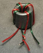
sort of..I have 4 winds and then a center tap, and then another 4 winds. The primary leads that are driven by the FETS end up next to each other back at the starting point, while the CT is on the opposite side. Same goes for the secondary.
here is a photo:
http://getchellaudio.googlepages.com/play009.jpg
here is a photo:
http://getchellaudio.googlepages.com/play009.jpg
That seems to have the primary windings in phase instead of out of phase. I don't think that will work.
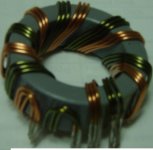
Wind a set of primaries onto the other core you have using a layout like the one in the photo I posted. Don't wind a secondary.
Wind a set of primaries onto the other core you have using a layout like the one in the photo I posted. Don't wind a secondary.
Perry Babin said:That seems to have the primary windings in phase instead of out of phase. I don't think that will work.
Good observation ther Perry Babin, I missed that. Being in phase will cause the core to saturate in a cycle or two, it will have to be re-wound.
Perry Babin said:That seems to have the primary windings in phase instead of out of phase. I don't think that will work.
I may have to disagree.
if you notice, there are four terminals on the resulting transformer primary, if you have observed, the two near the middle are joined together and acts as the center tap. the two at the sides are connected to the fets.
if you follow the wire colors and turn direction closely, they are opposite and not in phase. I wind my transformers exactly the same way (and so does most car amp manufacturers) and they all work. 🙂
an advatage here is that they are almost bifilar wound and that is a good thing. 😉
djQUAN said:
I may have to disagree.
if you notice, there are four terminals on the resulting transformer primary, if you have observed, the two near the middle are joined together and acts as the center tap. the two at the sides are connected to the fets.
if you follow the wire colors and turn direction closely, they are opposite and not in phase. I wind my transformers exactly the same way (and so does most car amp manufacturers) and they all work. 🙂
an advatage here is that they are almost bifilar wound and that is a good thing. 😉
djQUAN, I just made a test circuit and transformer the way it is in ThSpeakerDude88 picture and the mosfets heat up badly and the waveform looks like it got ran over a few dozen times.

The setup
The waveform (See how there in phase, there not suposed to be)
And when I used a different core (with the other winding way that Me and Perry are talking about I get this)
Pic of the setup
And for the waveform: (these ones are out of phase)
P.S the scope is set to the same setting for both test but some reason test #1 dropped in freq.
The top waveform looks like the frequency changed because you get a peak each time EITHER output is switched off. The peak voltage is limited by the reverse breakdown voltage of the intrinsic zener in the FET. If you used 100 volt zeners, the voltage would have gone higher.
For those who are looking at the vertical amplifier settings (volts/div), the scope is actually showing 20v/div instead of 2v/div. The probe is is a switchable probe and is set to 10x. If this were a 10x probe with the resistor in the BNC connector, the scope would have switched to 20v/div (the 20 would be lit instead of the 2).
For those who are looking at the vertical amplifier settings (volts/div), the scope is actually showing 20v/div instead of 2v/div. The probe is is a switchable probe and is set to 10x. If this were a 10x probe with the resistor in the BNC connector, the scope would have switched to 20v/div (the 20 would be lit instead of the 2).
- Status
- Not open for further replies.
- Home
- General Interest
- Car Audio
- Low Power: TL494 or SG3525?