I have this board with several frequency filters.
The one I am wanting to modify is this one.
What my intention is to bring the trigger (center) frequency down to about 50 to 75Hz, from the current 300Hz.
I don't have Spice or any of those apps, but could someone look at this circuit, perhaps suggest what part values to change for the modification.
Thanks in advance.
Attachments
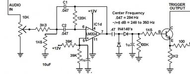
Changing both C1 and C2 to 0.22uF gives you a center frequency of 55Hz, with 0.27uF it'll be 65Hz.
Regards,
Braca
Regards,
Braca
Scaling frequency is easy with analog filters, you just scale the R's, L's, and C's independently to control frequency and impedance.
Impedance scales with R, L, and 1/C and frequency with 1/L and 1/C
So for an RC filter you can just change the C's in step to change the frequency
without affecting the impedance.
In an LC filter you could for instance double all the L's and all the C's to lower the frequency by a factor of 4 without changing the impedance.
The farad unit is equivalent to seconds/ohm - or 1 / (ohm hertz)
The henry unit is equivalent to ohm seconds - or ohm/hertz
Thanks Mark.
So would you go with DNI's suggestion above, with the cap changes?
I don't want to tear into the board, keeping things simple as possible for the right changes.
You see, the board is very tightly packed, and even changing the caps is a delicate procedure.
I even thought of adding "jumper caps" on the bottom of the board across of the existing ones.
This circuit allows the variation of resonance without changing the gain.
The 1k5 canbe replaced by a 5k pot with 470R in series.
With C1.2 =200n (150n in parallel) you get these curves

the level pot also has some impact on the resonance, you will have realized that. I depicted the most (50%) and least (100%) cases
no need to change the output caps
The 1k5 canbe replaced by a 5k pot with 470R in series.
With C1.2 =200n (150n in parallel) you get these curves
the level pot also has some impact on the resonance, you will have realized that. I depicted the most (50%) and least (100%) cases
no need to change the output caps
Last edited: