I'm trying to figure out the best way to get an ultra-low noise split noise power supply for a microphone amplifier driven by a LME49990. Right now I'm looking at several options:
I've come across some example power supply designs on this forum and elsewhere; however, they all involve using an AC to DC transformer. I would much prefer not to work with line voltage directly as I am not comfortable doing so. Furthermore, it's best for the AC to DC transformer to be as far away from the experiment rig as possible (the experiment is very susceptible to the EM radiated from the AC to DC transformer).
- Use an isolated DC DC converter (e.g., the Hammerhead, Hammerhead* | GE Industrial Solutions) to generate the +/-15V rails and then use a TPS7A4700 and TPS7A33 LDO voltage regulators to bring the rail down to +/-14V (or +/-12V). Personally, I'd prefer to find a DC DC DC converter that produced more than +/-15V so I could use the LDO voltage regulators to bring the rail down to a clean +/-15V supply. However, converters providing more than +/-15V are very expensive.
- Use a DC power supply with greater than 30V, generate a virtual ground (Imgur: The most awesome images on the Internet) and use the TPS7A4700 and TPS7A33 LDO voltage regulators to clean up the rails and generate +/-15V output voltage.
- Use a DC power supply with more than 30V and use two TPS7A4700 LDO voltage regulators. One would be set to +30V, the other to +15V. Then, the one outputting +15V would be the "ground" for the circuit.
- Use a commercially available dual power supply (any recommendations?) to feed into the TPS7A4700 and TPS7A33 LDO voltage regulators.
- Alternatively, should I look into using batteries? Any recommendations?
I've come across some example power supply designs on this forum and elsewhere; however, they all involve using an AC to DC transformer. I would much prefer not to work with line voltage directly as I am not comfortable doing so. Furthermore, it's best for the AC to DC transformer to be as far away from the experiment rig as possible (the experiment is very susceptible to the EM radiated from the AC to DC transformer).
If you are using dual 12 to 22Volt rails, it doesn't matter as the IC will reject any power supply noise. It just needs to be reasonably ripple free.
Don't waste your time and effort in making ultra clean supply rails as there is no need.
Don't waste your time and effort in making ultra clean supply rails as there is no need.
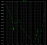
If you insist on connecting a DC/DC switchmode power converter to a microphone preamp, I recommend installing a LOT of RF filtering between the switcher and the downstream circuitry. If you have LTSPICE you can use the giant array of presupplied inductor models* from Wurth and others, to simulate your filters and quantify the amount of attenuation you'll get between 20kHz and 10 MHz. I suggest you aim for at least 100dB. Then, when you've got an RF-clean raw supply you can apply it to a modern, low-noise-in-the-audio-band, voltage regulator IC. The regulator output supplies power to the LME49990.
A low cost way to get even more RF attenuation, pretty darn good RF attenuation, is to build a capacitance multiplier stage out of a low-fT darlington. Make the RC lowpass cutoff frequency at the base node, equal to 2 Hertz. R is set by required-base-current at min-Beta, while C is set by (R*C > 80 milliseconds). Toss in a couple protection diodes to give well behaved startup and shutdown, done. The BDW42/47 complementary pair looks like a wonderful choice. (datasheet). One dollar american money @ qty=1 @ digikey.
*Left click on the inductor symbol and then click the "Select Inductor" pushbutton. Marvel at the sheer number of choices.
I don't have to use a DC/DC switchmode power converter. I'm perfectly happy using a linear regulated power supply (if I can find one) or using batteries. Are batteries generally a good option for a microphone preamp? If I use batteries, would adding a linear regulator (e.g., TPS7A4700 and TPS7A33) help clean up the battery voltage or only introduce more noise?
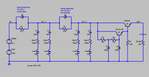
Here's a back-of-the-envelope sketch of the idea, slung together between my first and second cups of coffee this morning. Although it illustrates the basic concept, I'm sure there have got to be at least a half dozen places inside where it can be improved, optimized, polished, and superceded. But even this modest little caffeine-hallucination, mows down quite a bit of SMPS high frequency noise.
This circuit is upstream of the analog linear regulator. SMPS ---> this idea ---> analog voltage regulator.
_
This circuit is upstream of the analog linear regulator. SMPS ---> this idea ---> analog voltage regulator.
_
Attachments
2x 12V batteries, and use pcb that follows recommendations for bypassing, and keep all in screened enclosure. No need for regulators. KISS for starters.
In his other thread on the other website he discloses that several boards are connected to this supply and the total current is more than 750 milliamps. That might require large batteries, frequent recharges, or both.2x 12V batteries, and use pcb that follows recommendations for bypassing, and keep all in screened enclosure. No need for regulators. KISS for starters.
_
Attachments
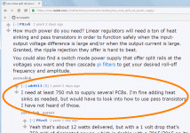
Yes. I need more than 750 mA. I'm fine purchasing some large batteries. I was looking into the LifePO4. They look very interesting. Would I still use a LDO regulator or do these just add noise into the circuit?
They don't have to be connected. They feed into a NI with 24-bit ADC/DACs. The ADC/DACs can be set to differential mode, so all the devices can float relative to earth ground. So, I could buy a bank of batteries (one for each device).
The devices are:
* Dual speaker drivers (to a headphone speaker). Requires up to 250 mA per speaker.
* Single microphone amplifier. Probably does not require more than 50 mA.
* The extra current was overhead just in case I need additional circuits to be integrated later.
The devices are:
* Dual speaker drivers (to a headphone speaker). Requires up to 250 mA per speaker.
* Single microphone amplifier. Probably does not require more than 50 mA.
* The extra current was overhead just in case I need additional circuits to be integrated later.
There are ready made regulators with +-15V based on TPS7A4700. Or anywhere else.
Buy one and use it from dual secondary trasformer with big reserv caps.
Buy one and use it from dual secondary trasformer with big reserv caps.
For low noise an ac voltage doubler takes some beating. Plug top ac output transformers are easily available from farnell. Look at ESP project p05 as an example.
- Status
- Not open for further replies.
- Home
- Amplifiers
- Power Supplies
- low noise split power supply