@kotlarix
I think you will need a 9V AC transformer minimum. What DC voltage output are you aiming for?
I think you will need a 9V AC transformer minimum. What DC voltage output are you aiming for?
I'm aiming 6V 0,07A. Transformer is 20 VAC have two outputs sec I:6V and sec II:5V. For 5V I have EU made psu circuit and this one works well
Try connecting your secondaries in series which will give AC in of 11V, then see if you can adjust the pot for 6V DC out.
Try connecting your secondaries in series which will give AC in of 11V, then see if you can adjust the pot for 6V DC out.
@kotlarix ...and don't forget that you may need to use a larger heatsink in order to help the dissipation of the extra heat generated by dropping the CC voltage from 11VAC x 1.41= 15.5VCC to 6VCC
I'll dropped my pistol soldiering machine yesterday 🙁 so I'm blocked till Tuesday (ordered soldiering station) then I'll let you guys know what it comes after connecting transformer in series and connecting it to the PSU.
Guy from China said 9V it's minimum requirement for this PSU circuit.
Device I'm trying to connect with this PSU is Digione Signature recommended voltage is 5-6V DC 0.065A. I checked voltage from LiFEpo4 battery pack (4pcs) they sell and recommend to use for best results in SQ and it's 7.27V when fully charged so I assume that board can handle more than they claim (probably safety reasons).
I wonder because now I get from transformer 6V AC when connecting to PSU circuit I get 7.3V DC if it have chance to work with Digione hat? Thing that bothers me most is that I desoldired L contacts on circuit but I still have DC at the output (was thinking that circuit will only give the DC when contacts are solidiered).
I'll dropped my pistol soldiering machine yesterday 🙁 so I'm blocked till Tuesday (ordered soldiering station) then I'll let you guys know what it comes after connecting transformer in series and connecting it to the PSU.
Guy from China said 9V it's minimum requirement for this PSU circuit.
Device I'm trying to connect with this PSU is Digione Signature recommended voltage is 5-6V DC 0.065A. I checked voltage from LiFEpo4 battery pack (4pcs) they sell and recommend to use for best results in SQ and it's 7.27V when fully charged so I assume that board can handle more than they claim (probably safety reasons).
I wonder because now I get from transformer 6V AC when connecting to PSU circuit I get 7.3V DC if it have chance to work with Digione hat? Thing that bothers me most is that I desoldired L contacts on circuit but I still have DC at the output (was thinking that circuit will only give the DC when contacts are solidiered).
You need a minimum 9VAC indeed (for feeding the regulator board). Check the secondary AC voltages WITHOUT any load (the regulator board un-connected) and afterwards check again with the board connected. Possible problems: 1. If the regulator board is pulling too much current the secondary AC voltage will drop (don't forget about that minimum 9VAC), will get hot and it may catch fire. MAKE SURE YOU FIT the necessary fuses on the mains LIVE wire leading the transformer's primary and between the transformer's new secondary and the one of the board's AC IN (this fuse is just for being extra cautious, if you don't mind) 2. You'll have the transformer's two secondary windings linked in 'series' providing a possible 11VAC (no load). If one of the two windings will not be able to provide the current required by the regulator board the secondary's voltage will drop again. If all's well disconnect from the mains and place a 1-2W resistor (value > 2kOhm) between the V+ and V- connectors for discharging any stored DC voltage. Connect regulator board to the Allo DigiOne Signature combo, power up and check the voltages again (VAC and V+).
Sec I: 5.4V AC (without load) Sec II: 6V AC (without load). After connecting in series is 12.1V (without load). You think is enough to deliver 6.4V DC 0.07A?
I probably soldiered one LED wrong direction, tomorrow I'm getting soldiering station so I'll go over the board at the evening.
Gladly I bought two kits so if I fry one I'll make second��
I probably soldiered one LED wrong direction, tomorrow I'm getting soldiering station so I'll go over the board at the evening.
Gladly I bought two kits so if I fry one I'll make second��
Received my board for about 10 days, use it to drive rbp 3b+ running moode connecting to an usb dac, the result is outstanding. So I spent some time study the circuit, run some simulation and do some mods on the board, here is some experience I would like to share:
(1) I modified the original circuit diagram to reflect where the clone board is different from the original one. Also each functional block is outlined with different colors.

*I forgot to change C105 to 47u for the clone board.
(2) Minimum 9V AC is required to properly power the board, since TL072 need at least 10V for Vcc+ - Vcc-.
(3) To configure the output voltage, use the following formula.
[Vout - Vin+] = Vref * (R127 + R126 + R125)/(R127 + R126min~max) = Vout * R115/(R115 + R119 + Rrange)
--- Rrange is the combined value of R122, R123, R301
--- Vref is voltage across reference red led DL301
with real values substituted,
[Vout - Vin+] = 1.938V ~ 2.193V ~ 2.525V, @Vref = 1.8V (usual forward voltage for red led)
and
Vout = Vref * (46.3k)(5.5k + Rrange)/(33k ~ 43k)(3.3k)
or tabularize the different combinations of Rrange:
Range__H___M____L____Vout (V), @Vref = 1.8V
2.5k____x____x____x_____4.70 ~ 6.12
2.7k_________x____x_____4.82 ~ 6.27
2.98k___x_________x_____4.98 ~ 6.49
3.3k______________x_____5.17 ~ 6.73
10.3k___x____x__________9.28 ~ 12.09
15k_________.x_________12.04 ~ 15.68
33k____.x______________22.61 ~ 29.46
Note: this is based on Vref = 1.8V, on my board the measured value is around 1.875, with L point soldered, the lowest reached voltage is 5.17*1.875/1.8 = 5.39, too high for 5V supply, I also have to solder M point to bring the output to 5V.
From the table, one can see it doesn't cover the full range, e.g. there is no way to adjust to 18V. In this case, you better install your own resistor use the following formula:
Rrange = {Vout/Vref) * (3.3k)(33k ~43k)}/(46.3k) - 5.5k
To generate 18V, Rrange = (18/1.8)*3.3*38/46.3 - 5.5 = 21.6k (use 21.5k standard 1% value). You can replace any of H, M, L resistors and with the corresponding point soldered on.
(4) About the maximal current it can supply, with some simulation (thanks to fabio1068 for the tina model)

From the simulation, the circuit start to fail between 1.67A to 1.83A. I'll suggest use it to drive at most 1.5A "peak" load.
(5) The noise figure: Since I only have a basic fluke multimeter and its minimal voltage resolution is 0.1mV, so this result is a rough estimation. After some modifications with the board, the following figures are measured.
rbp 3b+ + usb dac, music not playing, 0mV @terminal, 0mV @rbp 3b+ (< 50uV ?)
rbp 3b+ + usb dac + usb hard drive (use external usb hub swithing power), music not playing, 0.1mV@terminal, 0.1~0.2mV @rbp 3b+
rbp 3b+ + usb dac + usb hard drive (use external usb hub swithing power), music playing, 0.1~0.2mV@terminal, 0.2~0.5mV @rbp 3b+
*total current is about 0.5A
(6) The modifications I made on the board:
(A) The layout of the board is pretty bad, the measured resistance between input (right after rectifier diode) and output terminal (Vout) is around 14 mOhm, so I strengthen both power lines (yellow marked lines in the circuit diagram) with solid wires.
(B) Add 0.47u caps across the 4 input rectifier diodes.
(C) Earth the input ground (p1/8,9 in the circuit diagram) with a 0.01u cap.
(D) Use a line filter before the transformer.
(E) Change R102 from 10k to 5k. This is not about reducing noise, more about put 5.1V zener at proper operating point (~1.5mA), especially when drive the board with 9V AC.
The above is what I have done so far, hope my experience can help others.
(1) I modified the original circuit diagram to reflect where the clone board is different from the original one. Also each functional block is outlined with different colors.
*I forgot to change C105 to 47u for the clone board.
(2) Minimum 9V AC is required to properly power the board, since TL072 need at least 10V for Vcc+ - Vcc-.
(3) To configure the output voltage, use the following formula.
[Vout - Vin+] = Vref * (R127 + R126 + R125)/(R127 + R126min~max) = Vout * R115/(R115 + R119 + Rrange)
--- Rrange is the combined value of R122, R123, R301
--- Vref is voltage across reference red led DL301
with real values substituted,
[Vout - Vin+] = 1.938V ~ 2.193V ~ 2.525V, @Vref = 1.8V (usual forward voltage for red led)
and
Vout = Vref * (46.3k)(5.5k + Rrange)/(33k ~ 43k)(3.3k)
or tabularize the different combinations of Rrange:
Range__H___M____L____Vout (V), @Vref = 1.8V
2.5k____x____x____x_____4.70 ~ 6.12
2.7k_________x____x_____4.82 ~ 6.27
2.98k___x_________x_____4.98 ~ 6.49
3.3k______________x_____5.17 ~ 6.73
10.3k___x____x__________9.28 ~ 12.09
15k_________.x_________12.04 ~ 15.68
33k____.x______________22.61 ~ 29.46
Note: this is based on Vref = 1.8V, on my board the measured value is around 1.875, with L point soldered, the lowest reached voltage is 5.17*1.875/1.8 = 5.39, too high for 5V supply, I also have to solder M point to bring the output to 5V.
From the table, one can see it doesn't cover the full range, e.g. there is no way to adjust to 18V. In this case, you better install your own resistor use the following formula:
Rrange = {Vout/Vref) * (3.3k)(33k ~43k)}/(46.3k) - 5.5k
To generate 18V, Rrange = (18/1.8)*3.3*38/46.3 - 5.5 = 21.6k (use 21.5k standard 1% value). You can replace any of H, M, L resistors and with the corresponding point soldered on.
(4) About the maximal current it can supply, with some simulation (thanks to fabio1068 for the tina model)
From the simulation, the circuit start to fail between 1.67A to 1.83A. I'll suggest use it to drive at most 1.5A "peak" load.
(5) The noise figure: Since I only have a basic fluke multimeter and its minimal voltage resolution is 0.1mV, so this result is a rough estimation. After some modifications with the board, the following figures are measured.
rbp 3b+ + usb dac, music not playing, 0mV @terminal, 0mV @rbp 3b+ (< 50uV ?)
rbp 3b+ + usb dac + usb hard drive (use external usb hub swithing power), music not playing, 0.1mV@terminal, 0.1~0.2mV @rbp 3b+
rbp 3b+ + usb dac + usb hard drive (use external usb hub swithing power), music playing, 0.1~0.2mV@terminal, 0.2~0.5mV @rbp 3b+
*total current is about 0.5A
(6) The modifications I made on the board:
(A) The layout of the board is pretty bad, the measured resistance between input (right after rectifier diode) and output terminal (Vout) is around 14 mOhm, so I strengthen both power lines (yellow marked lines in the circuit diagram) with solid wires.
(B) Add 0.47u caps across the 4 input rectifier diodes.
(C) Earth the input ground (p1/8,9 in the circuit diagram) with a 0.01u cap.
(D) Use a line filter before the transformer.
(E) Change R102 from 10k to 5k. This is not about reducing noise, more about put 5.1V zener at proper operating point (~1.5mA), especially when drive the board with 9V AC.
The above is what I have done so far, hope my experience can help others.
Last edited:
@bButcher
That's very useful information. Thank you.
I'd like to look at your pics, but I'm unable to open them.
That's very useful information. Thank you.
I'd like to look at your pics, but I'm unable to open them.
Sorry, haven't post anything for years, forget how to post a picture. I drag and drop the picture files (PNG files) into the message, it didn't seem to work.
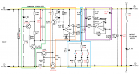
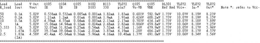
Regarding to 1.5A limitation, with further investigation one can see it is because D102, D103 serve as limiter, so the circuit is designed to maximally provide 1.5A output current.
With D102 & D103 removed and continue the simulation, now the circuit can provide up to 2.5A and fail again before 3A.
With D102 & D103 removed and continue the simulation, now the circuit can provide up to 2.5A and fail again before 3A.
Attachments
bButcher can post picture of your board top and bottom? (I'm not electronic engineer) and have some difficulties with reading and understanding electronical schematics.
I'm preparing to soldiering now and it would be very helpful to apply your upgrades on board I wil soldier.
I'm preparing to soldiering now and it would be very helpful to apply your upgrades on board I wil soldier.
@ kotlarix
My is a single power version, if you have a dual power version, the layout is almost the same, at least the power lines part.
My is a single power version, if you have a dual power version, the layout is almost the same, at least the power lines part.
Attachments
@gigigirl,
Yes, it work. I did a real test with Flathead signal 20V transformer (LP-20-2400) and a dummy load 30ohm/20W. Measured values are: AC input 21.94V, DC output 24, load current 810mA. DC voltage after rectifier is 25.2V, just enough to keep output regulated, so for your application I will recommend a 24VAC output transformer.
Yes, it work. I did a real test with Flathead signal 20V transformer (LP-20-2400) and a dummy load 30ohm/20W. Measured values are: AC input 21.94V, DC output 24, load current 810mA. DC voltage after rectifier is 25.2V, just enough to keep output regulated, so for your application I will recommend a 24VAC output transformer.
@gigigirl
That doesn't look suitable. The stated max current is only 0.62A and you require 0.8A I think?
Edit: The current limit is probably set by the transformer they supply with it.
That doesn't look suitable. The stated max current is only 0.62A and you require 0.8A I think?
Edit: The current limit is probably set by the transformer they supply with it.
Last edited:
Thx for pictures bButcher it will help me a lot
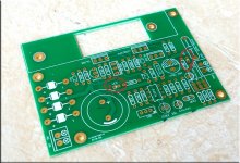
Can you clarify to me how to soldier led I don't understand marking on PCB (probably that's why my first one it's broken).
Can you clarify to me how to soldier led I don't understand marking on PCB (probably that's why my first one it's broken).
An externally hosted image should be here but it was not working when we last tested it.
@gigigirl,
Sorry, the unit is not suitable because it uses 15VA transformer so the current it can supply maximally @24 is 15/24 = 0.624A. You should look for at least a 25VA unit. The LP-20-2400 transformer I did the test for you is a 48VA model.
Sorry, the unit is not suitable because it uses 15VA transformer so the current it can supply maximally @24 is 15/24 = 0.624A. You should look for at least a 25VA unit. The LP-20-2400 transformer I did the test for you is a 48VA model.
@ kotlarix
Can't open your picture. But usually the led pin out is like this: Electronics 2000 | Pin-outs | LEDs, the longer pin is +. Even you install it the wrong way, it should not burn the whole module, just remove it and correct it.
Can't open your picture. But usually the led pin out is like this: Electronics 2000 | Pin-outs | LEDs, the longer pin is +. Even you install it the wrong way, it should not burn the whole module, just remove it and correct it.
Attachments
Last edited:
- Home
- Amplifiers
- Power Supplies
- low noise Pre-Amp / DAC power supply MJE15034 TL072 Regulator based on STUDER 900