LM317 model.
00940.
you have any LM338 spice model?
This is the highest current version of LM317 type regulator.
00940.
you have any LM338 spice model?
This is the highest current version of LM317 type regulator.

could you please post your schematic ? I'll try it here in LTspice to see what I'm doing wrong.
and I'm sorry but I don't have the lm338 model.
edit: nevermind, I found what was wrong. I'll post the updated graphs later on.
and I'm sorry but I don't have the lm338 model.
edit: nevermind, I found what was wrong. I'll post the updated graphs later on.
Hi Ben,
in your corrected version, we are at -12dB @100kHz, in my case, the most simple configuration thinkable, it's -60dB. This is a huge difference, and I'm not sure what goes on. Have you disabled I1 for that sim?
Rüdiger
in your corrected version, we are at -12dB @100kHz, in my case, the most simple configuration thinkable, it's -60dB. This is a huge difference, and I'm not sure what goes on. Have you disabled I1 for that sim?
Rüdiger
Onvinyl said:Hi Ben,
in your corrected version, we are at -12dB @100kHz, in my case, the most simple configuration thinkable, it's -60dB. This is a huge difference, and I'm not sure what goes on. Have you disabled I1 for that sim?
Rüdiger
I really thought I did but, running the sims one more time, it seems I didn't.
 I probably messed up while playing with values to avoid that stupid "iterations limit reached" error. It's really a frustrating exercise.
I double checked everything this time and here is what I get. There is still some difference as I don't drop as much voltage over the lm317 (why do you use a 50-70V input ?). Using exactly your values, I've got a perfect match.
Now, the stripped down superreg also performs way better, but those results are completly unrealistic in real life. To be honnest, I use a lower esr cap for the superreg output (0.16r).
Attachments
00940
if you look at the actual audio bandwidth, it is still good.
I mean, who can hear what is above 15 kHz?
I cant. You cant! Try and see if you can. I did.
As I am of age ( soon 60 years old ) I am restricted to listen to anything less than 12 kHz, but nothing else.
But I say your last posted sim is quite acceptable for a less sofisticated solution.
I have seen commercial chips with a lot worse performance curves.
Hi,
ensure that R5 + R6 and D1 + D2 are connected as threequarters of a measuring bridge.
And just as importantly that NOTHING contaminates the measuring bridge currents, or their connections to the voltage monitoring points.
ensure that R5 + R6 and D1 + D2 are connected as threequarters of a measuring bridge.
And just as importantly that NOTHING contaminates the measuring bridge currents, or their connections to the voltage monitoring points.
Hi,
It looks a bit odd. I Think I see what you are trying to do, the Opamp sinking current from the pass transistor drive. Have you tried adding a pulsed variable load on the output to check the regulation under dynamic conditions ( just a few 10's of milliamps ). You have a lot of very large time constants in there 🙂
It looks a bit odd. I Think I see what you are trying to do, the Opamp sinking current from the pass transistor drive. Have you tried adding a pulsed variable load on the output to check the regulation under dynamic conditions ( just a few 10's of milliamps ). You have a lot of very large time constants in there 🙂
Mooly: OK. I replaced the load resistor by a variable load. It's swinging from 80ma to 120ma at 15KHz. I also removed the output capacitor. Here's the result... The time constants play at startup: 400ms to reach a stable state.
AndrewT: I don't quite get it... I planned to join all the ground together at a star except at D2 and R6, those two being joined together apart. I would then wire the ground in that order : big filter caps of the PS, "groundstar", junction of D2 and R6, load.
AndrewT: I don't quite get it... I planned to join all the ground together at a star except at D2 and R6, those two being joined together apart. I would then wire the ground in that order : big filter caps of the PS, "groundstar", junction of D2 and R6, load.
Attachments
Hi,
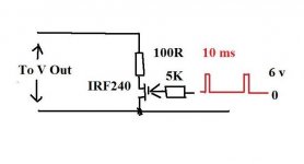
Try something like this as a load. Change the value of the 100R to draw the max current the regulator is designed for. You need a much lower test frequency to see how the regulation behaves. You have to see what happens when there is a sudden change in the current drawn by the load say from zero to it's maximum rated current and vice versa as a "single" event. I don't ( as yet ) have any experience with simulators, but I see V1 and V2 appear to be shown as an AC source 🙂
Whats your graph showing -- is the red trace the output voltage and the blue the same with the variable load attached ?
Attachments
The red trace is the output voltage under load and the blue trace the current draw 😀
I'll try with your load and report back. I also tried some "pulse" current source at the output, jumping from 100 to 150ma at DC every 1ms and the output voltage didn't move at all.
I'll try with your load and report back. I also tried some "pulse" current source at the output, jumping from 100 to 150ma at DC every 1ms and the output voltage didn't move at all.
AndrewT said:Hi,
ensure that R5 + R6 and D1 + D2 are connected as threequarters of a measuring bridge.
And just as importantly that NOTHING contaminates the measuring bridge currents, or their connections to the voltage monitoring points.
the inputs to the opamp are the side nodes of a Wheatstone bridge.00940 said:
AndrewT: I don't quite get it... I planned to join all the ground together at a star except at D2 and R6, those two being joined together apart. I would then wire the ground in that order : big filter caps of the PS, "groundstar", junction of D2 and R6, load.
The top and bottom nodes of the Wheatstone bridge are the measuring/monitoring points. These must be arranged to measure the output at the appropriate points. No other circuit or ground current can be allowed to use any part of the wiring/traces that form the Wheatstone bridge.
Yes, you can star connect the power side and star connect the ground side but you MUST ensure integrity of the bridge measuring circuit.
If you go back to Jan & Walt's super reg you will see they have a full 4 sided bridge. Look at Jan's PCB layout, there the top and bottom nodes are taken to the output points, maintaining integrity of the measurements.
Allright, here is the result for a variable current source made of discrete parts. Still no output capacitor. Green is the output voltage, red the current drawn.
I should add some serie resistance/inductance to simulate the wiring but it's good enough for me.
I should add some serie resistance/inductance to simulate the wiring but it's good enough for me.
Attachments
- Status
- Not open for further replies.
- Home
- Amplifiers
- Power Supplies
- Low cost regulator in between Jung and Flea