The idea about this reg came in another thread, with a misleading title (http://www.diyaudio.com/forums/showthread.php?s=&threadid=126361 ), so I'll post it here.
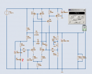
As said in the title, the sources of inspiration are the Jung regulators article and the "Flea" regulator designed by Martin Clark on PFM. From Jung, I took the ccs for the pass transistor. From Martin Clark, the idea of using a 3pins reg as ccs for the voltage reference.
If anyone sees obvious errors or improvements (keeping in mind that it's supposed to stay cheaper than a full-blown Jung), I'd be glad to hear them before breadbording the reg. 🙂
Attachments
Hi,
what would happen if you doubled up D1 or replaced it with a LED?
Is 5.4mA passing R6 enough?
What about some noise attenuation cap across the Zener?
and a big cap on the adj pin?
what would happen if you doubled up D1 or replaced it with a LED?
Is 5.4mA passing R6 enough?
What about some noise attenuation cap across the Zener?
and a big cap on the adj pin?
The output of the opamp is pushed further away of the supply. So, what comes to mind:AndrewT said:what would happen if you doubled up D1 or replaced it with a LED
- swap D1 and D2 to reduce the dropout by around 1V but then the input voltage from the reference would be close to the rail, certainly too close (2V).
- or replace D1 by a led and the ne5534 will work in a safer area.
Well, it depends on the hfe of the bd139 used. It must be adjusted in order to limit the current that can pass through the pass transistor. I'd set the limit at around 300ma, for a max dissipation of 1W. One could simply set the resistor according to the "worst case scenario". For a bd139-6, the worst beta is 40, according to the datasheet, so you need around 8ma.Is 5.4mA passing R6 enough?
The zener's noise is attenuated where it matters most by the RC filter at the input of the ne5534.What about some noise attenuation cap across the Zener? and a big cap on the adj pin?
A big cap from adjust to ground would certainly improve the performance of the prereg, which is good for the error amp. But then, I need to add protection diodes, to protect the lm317.
So, what needs to be changed:
- change D1 for a led,
- adjust R6 according to the bd139 at hand,
- add a cap at the adjust pin (100uf being ok),
- add a pair of protection diodes around the lm317 (1n4001).
00940 said:[snip]- or replace D1 by a led and the ne5534 will work in a safer area.
[snip]
... and then you can supply the opamp from the regulated output for even better performance.
Jan Didden
janneman said:... and then you can supply the opamp
from the regulated output
This is of course the ultimate way.
And one of the main features of Jung Super Regulator.
In this schematic, originally drawn for keantoken in this topic:
http://www.diyaudio.com/forums/showthread.php?postid=1551799#post1551799
.. I use the output to fead the REFERENCE Red LED.
This is a great improvement to many other ways 🙂
Feeding the complete op-amp, discrete or chip op,
from the output is even better, of course!
Attachments
janneman said:... and then you can supply the opamp from the regulated output for even better performance.
Jan Didden
I'm affraid it won't work without major changes. Since the opamp is working at unity gain, the reference voltage would be equal to the output voltage.
Now, it might work if :
- I use the 5534 with some gain (which means another extra cap to reduce ac gain at unity).
- change D1 for a zener (and I probably must bypass it).
- change D4 for something like a 6.2V zener and D2 by a 12V zener.
I'm affraid of startup problems with such a configuration

00940 said:
I'm affraid it won't work without major changes. Since the opamp is working at unity gain, the reference voltage would be equal to the output voltage.
Now, it might work if :
- I use the 5534 with some gain (which means another extra cap to reduce ac gain at unity).
- change D1 for a zener (and I probably must bypass it).
- change D4 for something like a 6.2V zener and D2 by a 12V zener.
I'm affraid of startup problems with such a configuration
No it isn't working unity gain. If you replace D1 with a zener of about half the Vout, the opamp output will sit neatly halfway the supply. Not often that you get a chance to increase performance for essentially zero cost 😉
Start-up *may* be an issue, but that can be cured easily. It's worth a try.
Edit: Even if you don't supply the opamp from the regulated output, it is still advisable to bias the opamp output midway of the supply voltage.
Jan Didden
Please forgive me but I wasn't clear again. I had not in mind the output voltage of the opamp, but of the regulator. What happen if my opamp is powered by 16.7V and the reference voltage is also 16.7V ??
The answer of LTspice is : it doesn't work (unless doing the changes described above).
Btw, you're right to correct me, the opamp isn't at unity I just meant I'm feeding the inverting input with the whole output voltage and the positive with a high voltage reference.
The answer of LTspice is : it doesn't work (unless doing the changes described above).
Btw, you're right to correct me, the opamp isn't at unity
I just meant I'm feeding the inverting input with the whole output voltage and the positive with a high voltage reference.
Another question... Do I have to keep the 22p compensation capacitor on the ne5534 ? It's needed for unity gain stability but is it needed here ?
Hi Ben,
interesting circuit. Do you mind to post some sim results like outputimpedance vs. frequency or line suppression vs. frequency?
keep it up!
Rüdiger
interesting circuit. Do you mind to post some sim results like outputimpedance vs. frequency or line suppression vs. frequency?
keep it up!
Rüdiger
Onvinyl said:Hi Ben,
interesting circuit. Do you mind to post some sim results like outputimpedance vs. frequency or line suppression vs. frequency?
keep it up!
Rüdiger
I don't mind but I don't really know how to do those simulations (I'm quite a newbie at LTspice, I only use the most basic functions). If you can give me some directions, it would be with pleasure.
For instance
-hitting right mouse button
- on context menue chose 'Edit Simulation Cmd.'
- chosse tab 'AC Analysis'
- Fill in e.g. '.ac oct 12 0.001 20000000000' where the las two numbers are start- and stop frequencies
Then, hit the 'Run' button at the toolbar. Then select the output node and you see a graph indicating how much down the regulator regulates.
You may sim the output impedance using the above method if you
- place a current source (I1, for instance) at the output node with AC=1 (and nothing else)
- type in the expression editor (insert your own node names here) .V(out)/I(I1) You can right click on the node name (V(out)) in the graphs window to get to the expression editor
-left-click on the dB-scale in the graphs window and chosse 'linear' in the option box.
Then you have the outputimpdedance vs. frequency plot
I hope I didn't forget something,
Rüdiger
00940 said:A schematic is better than a lot of words. Those two seem to work in the simulator.
Much better indeed. Now make the ref about 8V, and divide the output feedback to the opamp by two. That will make the opamp extremely happy 😉 .
With a bit of luck you can now delete the comp cap, or make it smaller.
Jan Didden
Wrt the sims: I'm sorry but the ne5534 model creates some problems. When I run the simulation, I get this msg: "analysis failed: iteration limit reached". Other opamps models work but as the results are widely different, I don't have anything interesting to offer you 🙁

This looks encouraging. May I ask where youre Model of the 317 is from?
In a first step I would compare the performance of a 317 regulator in it's standard form with your design.
You should introduce some serial resistance in your output cap, else your results might be too optimistic.
Rüdiger
In a first step I would compare the performance of a 317 regulator in it's standard form with your design.
You should introduce some serial resistance in your output cap, else your results might be too optimistic.
Rüdiger
- Caps and ESR: I was using for the 100uf caps a model with highish ESR (0.6R). The results below are for caps similar to the panasonic FM 100uF/25V (0.16R).
- LM317: the lm317 model is from the ltspice yahoo group, iirc. It came with the 337 model and an application circuit.
- The simulations results below are for a LM317 sitting on top of zener+cap. Simulations results are way better than for the usual resistor+cap at the adjust pin.
- LM317: the lm317 model is from the ltspice yahoo group, iirc. It came with the 337 model and an application circuit.
- The simulations results below are for a LM317 sitting on top of zener+cap. Simulations results are way better than for the usual resistor+cap at the adjust pin.
Attachments
- Status
- Not open for further replies.
- Home
- Amplifiers
- Power Supplies
- Low cost regulator in between Jung and Flea