Good philosophy Spartacus...do you participate to the group buy!? 😉
Yes, mine is half built, I hope to have time to be able to finish it off next weekend. I'll be using an external discrete supply, and doing a few mods.
Anyone can recommend a mouser code Dip8 socket ? I found some very expensive ones like 6 euro/unit.
I have an extensive collection of dip8 opamps i would like to test.
Sent from my iPad using Tapatalk
I have an extensive collection of dip8 opamps i would like to test.
Sent from my iPad using Tapatalk
I'm myself looking for a half decent PCB for the ES9018K2M, but this one doesn't seem to be it. From what I can see from the pictures, some return paths to the GND pins are long and sometimes almost funny: luckily there are for example the ground connections of the lock & AM LED's to make the connection to the bottom groundplane for one of the two DGND pins and decoupling of the oscillator is simply bad: ground and supply are connected each through a via and total loop is to be measured in centimeters...(scratch some paint and get C32 to the upper side). The ground return between DAC and oscillator is very long. I would also have used the thermal path underneath the chip for a low inductance connection to the bottom groundplane, but that doesn't seem to be the case. Ground is probably bouncing in some places, I would get the drill and add some via's around pin 1 and pin 20... or go with the pcb from DIYINHK (what I will probably do) if nothing else comes along
Last edited:
Trouble shooting is part of the fun! .... plenty of knowledge and experience around these parts to sort out these problems.
Hi I am wondering what you would do if your new washing machine has problems 😉 I like your positive view on matters though.
It occured to me that the chip itself may have issues regarding locking with its built in SPDIF port. In that case problems will be hard to solve. To be honest I am glad we don't use the chip in a new design (we intended to do so). I hope for all builders that the design will end up in being a fully functional bug-less excellent sounding device.
Last edited:
Try shielding. Also try turning various appliances, such as washing machines and lights, on and off to see if that triggers losing lock. Try a mains filter with transient suppressor prior to the transformer.
May be we can try:
- add a SMD ferrite bead somewhere before the ADM/ADP.
- add a EMI filter (eg. Schaffner) before the trafo.
CLC filtering is a must but I wonder if it helps enough in this case. You should try though. I hope you enjoy debugging the design as I think it was you that thought the implementation looked much better than our humble V3  Sorry that I had to chuckle
IMHO grounding and GND plane are the things to worry about. I would also keep the lower voltage power supplies separated from the +/- power supply and give the lower voltage regs their own separate winding from a transformer.
Sorry that I had to chuckle IMHO grounding and GND plane are the things to worry about. I would also keep the lower voltage power supplies separated from the +/- power supply and give the lower voltage regs their own separate winding from a transformer.
Last edited:
It occured to me that the chip itself may have issues regarding locking with its built in SPDIF port.
Resonessence Labs uses ES9018K2M in their Concero HD DAC so I doubt the chip's SPDIF have any issue.
Syllable's DAC is still one of the most most "complete" implementation where, to his credits he listened to users' requirements during the development stage and other than the filter caps grounding mod, I see no other major add-ons or mods are neccessary. It allows us to use a full IV stage which I believe is the only way to achieve maximum sound quality from any DAC.
My comparison comments are purely on technical side and I certainly respect your DAC execution nonetheless. Your input here are most welcomed and I think you should go ahead and come out with your own implementation.😉
Last edited:
It allows us to use a full IV stage which I believe is the only way to achieve maximum sound quality from any DAC.
As we say here: believing should be done in church 😉
It might just be that he lack of such an IV stage can work out the other way too... Don't expect a DAC from us with ES9018K2M. At least I won't be designing it, it seems a hard job as can be seen in this thread 🙂
Last edited:
Hi I am wondering what you would do if your new washing machine has problems 😉 I like your positive view on matters though.
Well it, is poor that there is no after sales support, but we are here now so have to deal with it.
It occured to me that the chip itself may have issues regarding locking with its built in SPDIF port. In that case problems will be hard to solve. To be honest I am glad we don't use the chip in a new design (we intended to do so). I hope for all builders that the design will end up in being a fully functional bug-less excellent sounding device.
I'm not sure we should blame the chip just yet, ESS' other parts work fine. I'll certainly be using the Wolfson though.
....few mods!??? tell me more!!!😀
The usual stuff such as opamps (ADA4898 for I/v), and caps (Silmics/Nichicons). I may replace the LM1117-5 with a 5V ADM7150. Some of the routing can be improved. I'd definitely recommend using a a low jitter SPDIF receiver. I've got some other ideas too, but I'll need to test them in my own build first.
I'm myself looking for a half decent PCB for the ES9018K2M, but this one doesn't seem to be it. From what I can see from the pictures, some return paths to the GND pins are long and sometimes almost funny: luckily there are for example the ground connections of the lock & AM LED's to make the connection to the bottom groundplane for one of the two DGND pins and decoupling of the oscillator is simply bad: ground and supply are connected each through a via and total loop is to be measured in centimeters...(scratch some paint and get C32 to the upper side). The ground return between DAC and oscillator is very long. I would also have used the thermal path underneath the chip for a low inductance connection to the bottom groundplane, but that doesn't seem to be the case. Ground is probably bouncing in some places, I would get the drill and add some via's around pin 1 and pin 20... or go with the pcb from DIYINHK (what I will probably do) if nothing else comes along
Have had a careful look at the grounding, and the above is good information - the grounding indeed is pretty bad. The good news is that it's all fixable with some mods to the PCB, which should quiet down the ground and reduce RF emissions. Whether these makes any difference to any lock issues or sound quality remains to be seen.
Just a thought, the original Buffalo had some big design issues, yet it still produced decent sound, and very good sound with mods, so is definitely not lost.
the above is good information
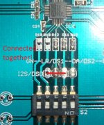
Thanks. Looking at the initial layout (http://i1301.photobucket.com/albums/ag103/audiodesine/IMG_5763_zps61f084ce.jpg and http://i1301.photobucket.com/albums/ag103/audiodesine/IMG_5784_zps02fe8123.jpg), overall ground was slightly better (although ground return of C21 is bad, ground should be on the top side to be close to the DGND-pin and ‘RST’ RC should have been moved more downwards to leave a wider trace to the second DGND-pin). Ground was partially messed up with the powersupply changes and the data lines from IC1 in this design ‘upgrade’. You don’t want noisy grounds, what would otherwise be the use of a clean power supply, good oscillator and all that stuff? I might start a pcb of my own, but the pitch of the dac is so narrow I won’t be able to etch it myself :-/ If you use I2S/DSD , improve the connection to DGND above the IC6-label: I would put the GND of the I2S on the right side of the connector and make a bridge over the reset line. Then there is the oscillator ground… well, this is DIY after all.
At the moment I'm looking at 3 vias, 2 near the DAC chip and 1 for I2S. A via at pin 1 should take care of the clock return. Would be useful to know if the ground pad of the DAC is connected to pins 1 and 21.
I'm glad some beads are used, as these will keep AC loops local to the nearest decouplers.
As per your suggestion, I've created a pad on the top ground plane next to the clock supply pad, will keep that loop nice and tight.
I'm glad some beads are used, as these will keep AC loops local to the nearest decouplers.
As per your suggestion, I've created a pad on the top ground plane next to the clock supply pad, will keep that loop nice and tight.
In the longer term, I'd be willing to take up a fresh layout with all grounding and layout improvements that are found to work here. My motivation is mainly to improve the analog section to use some larger parts (mini MELFs, SMD PPS capacitors, etc.). No schedules or timelines now, but I'll tentatively begin in a few months after populating and auditioning my board.
In the longer term, I'd be willing to take up a fresh layout with all grounding and layout improvements that are found to work here. My motivation is mainly to improve the analog section to use some larger parts (mini MELFs, SMD PPS capacitors, etc.). No schedules or timelines now, but I'll tentatively begin in a few months after populating and auditioning my board.
I look forwad to hearing about how you get on. I'm using 100nf PPS caps for AVcc and opamps. I'll probably add some Silmics to improve transient response. Would be good of course to have a PCB that had places for them.
- Status
- Not open for further replies.
- Home
- Source & Line
- Digital Line Level
- Low cost ES9018 Dac - Builders Thread