In the bottom row:
Rev W = C xxx
Rev V = E xxx
It seems that Rev V is the current production version.
Thanks
Have you tested it with AC input to the bridge rectifier section? I just checked the common node of C22 and C23, and it's floating (incorrectly) wrt to the ground plane, as stated by earlier posters. Without that ground, REG7 and REG8 regulators do not see rectified DC at their inputs, and are being operated out of spec - causing them to fail in many cases.
I'm not planning to use REG7 and REG8, but many others in the GB have paid for them, so you may want to at least offer spares to those whose regulators have failed.
I'm slowly building my dac and started with regulators. First phase was to populate the very few parts around the two main regulators Tps and connected to ground the floating middle point of the the two main filtering caps and surprises came. The positive regulator gave in the first moment 12 v and the one for negative rail 0,35v. Sometimes the positive regulator give me 16v the voltage fron input. From my point of view the problem is the poor quality of pcb or the poor quality of soldering used by @syllable to install the regulators and Ess dac chip. The solderings looks weard not like normal soldering they are dark grey and not smooth at all.
Tried to contact Syllable privately before writing this message but no reply.
I will ask a friend to try to desolder the two regulators with air gun and try to solder it back.
I will do first tests with an external +|-12v power supply but i feel cheated after this experience and refuse of support.
I feel the same, atupi. I would have given up on this project except that I really enjoy the sound of this dac, even with a simple psu. Instead of trying to rebuild the psu sector, I may try a psu board from this fellow, and then decide if I'll see it thru.
http://www.diyaudio.com/forums/powe...oise-symmetrical-psu-tps7a4701-tps7a3301.html
everyone will have to keep in mind not to buy anything from this indian seller in the future even if he might show up with a different username; I am happy that I haven't join that GB, I felt something fishy from the begining
... the poor quality of soldering used by @syllable to install the regulators and Ess dac chip. The solderings looks weard not like normal soldering they are dark grey and not smooth at all.
Yup, I noticed that. I thought it was due to lead-free solder. Maybe the flux was incompatible with the PCB plating.
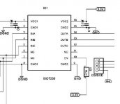
Can anyone explain to me what is the purpose of S1? It connects or disconnects the pin 10 (ENABLE) of I2S isolator from 3.3v voltage.
In datasheet pin 10 is shown to be permanently connected to 3.3v.
In datasheet pin 10 is shown to be permanently connected to 3.3v.
Attachments
Last edited:
Finished populating basic config with one spdif input and it worked about 10 minutes and now is complete quiet. After those 10 minutes started crackling left channel and after also right channel. On the next power up even spdif lock is gone.
All the best to Syllable who is not man enough to come here at least to try to clarify some things.
All the best to Syllable who is not man enough to come here at least to try to clarify some things.
Makes me wonder if it is worth the components cost to built this DAC..?
Is there another alternativ?
Is there another alternativ?
Finished populating basic config with one spdif input and it worked about 10 minutes and now is complete quiet. After those 10 minutes started crackling left channel and after also right channel. On the next power up even spdif lock is gone.
All the best to Syllable who is not man enough to come here at least to try to clarify some things.
That is not good to hear. I am almost ready to build mine as the parts gathering is finished but i am not so sure now. Where is Syllable?.🙁
Same here, one board already messed up by the regulator and now there seems to be other issue. Anyone successfully completly up and running?
No, it was messed up before the ground issue was identified, the second board is just sitting until I am more sure.
syklab,did you do the mod with grounding the psu e-lyts?(before the regulator messed up)
I did this grounding mod before powering up the regulators but the negative regulator was dead from start and the positive rail sometimes working and some others time no. Now it seems to work the one from positive rail after heated up a little bit the solderings. The this traces from pcb can be lifted in a second as they are pooresc quality ever seen in my diy er life. Even those i etch myself are much stronger.
Sent from my iPad using Tapatalk
Sounds like I will start by using the 4700 dual rail from diyinhk in tve second board, their site seems to be downed for a few days.
Anyway can anyone tell me what is the purpose of opamp IC5 ? That lm4562 used on the power supply of Avcc ?
Sent from my iPad using Tapatalk
Sent from my iPad using Tapatalk
Makes me wonder if it is worth the components cost to built this DAC..?
Is there another alternativ?
+1
Its shame tobe in this state... me too holding on to procuring other parts needed..
A noob question:
Can the output stage of this board directly drive Boston Accounstics A26 bookshelfs?
Or does it need a preamp + amplifier chain before signal can be passed to speakers?
Whoever tested appreciate your help to understand how and through what equipment the speakers are connected to test this board?
Can the output stage of this board directly drive Boston Accounstics A26 bookshelfs?
Or does it need a preamp + amplifier chain before signal can be passed to speakers?
Whoever tested appreciate your help to understand how and through what equipment the speakers are connected to test this board?
Same here, one board already messed up by the regulator and now there seems to be other issue. Anyone successfully completly up and running?
After some debug, mine works correctly! I can't say about sound because I use it on HC receiver with 5.1 speaker...my hifi system is active one and can't use DAC (I use DCX2496).
- Status
- Not open for further replies.
- Home
- Source & Line
- Digital Line Level
- Low cost ES9018 Dac - Builders Thread