http://frank.pocnet.net/sheets/123/3/38HE7.pdf (450 mA at 130V on g2, $1 tube, $0.35 in quantity, can run the pentode only with 21V across pins 10 and 12 for heater)
---
is this an undocumented feature of all brands ? none of the data sheets mentions it ...
Maybe some battery radio tubes survive because they are unusable/not-worth-it in practical projects? 😕
With due respect, I have been involved in this same type project, together with many others of course, including Merlin B , Steve Conner, Enzo and other distinguished Members, trying to help a German Engineer build a usable Tube Guitar Amp as his last project, his final Thesis, under safety rules imposed by his University.
Mind you, safety rules for graduating Engineers, not the general public which is presumed less trained !!!!!
Won't type again all that text, read all about it in:
Jcm800 Downscale
The thread is worth reading in full, lots of non conventional tubes were considered and analyzed.
A few notable points:
FWIW in USA (at least in California) even an experienced State Certified Electrician is allowed to work with only "less than 91V" circuits if he holds a "grade 7 (C7) contractor's certification"
But it was not Lawyer Land ... yet.
After that thread, a Forum member succeeded into building this:
two sobering comments:
With due respect, I have been involved in this same type project, together with many others of course, including Merlin B , Steve Conner, Enzo and other distinguished Members, trying to help a German Engineer build a usable Tube Guitar Amp as his last project, his final Thesis, under safety rules imposed by his University.
Mind you, safety rules for graduating Engineers, not the general public which is presumed less trained !!!!!
Won't type again all that text, read all about it in:
Jcm800 Downscale
The thread is worth reading in full, lots of non conventional tubes were considered and analyzed.
A few notable points:
😱Jcm800 Downscale
Hello community,
I'm trying to built a low power version of a Jcm800 for my bachelors thesis.
As my university limits me to working with voltages below 40 volts I can't take the meassurements on the JCM800 myself. I would need them to verify the simulation of the JCM800 I did.
Best regards from Germany,
Florian
FWIW in USA (at least in California) even an experienced State Certified Electrician is allowed to work with only "less than 91V" circuits if he holds a "grade 7 (C7) contractor's certification"
At my uni the safety limit is officially 50V, but they will go up to 60V if you're polite. Beyond that and you need to do a health and safety appraisal and build in various safety measures that make it nearly (but not quite) impossible to proceed.
FWIW compare this to my University safety rules ... of course 45 years ago, people smoked in class , etc.: we worked with live tube circuits, even open chassis oscilloscopes with a few thousand Volts inside, Electrical Machines lab test benches powered by 3 x 380VAC, the works.The 40 Volt limitation is an safty issue and a limit set by my university. It is states that no two points on the circuit can exeed this limit, so a +40/-40 design is out of limits as this clearly shows a maximum Voltage differential of 80 Volts. So for now 40V is the absolute limit. I could politly ask my proffessor for maybe 50 Volts, but I don't think that that would make a big difference therefore I will keep it to 40 for now.
But it was not Lawyer Land ... yet.
😀Yes, this post deviated into a "Find the weirdest tube" contest.
After that thread, a Forum member succeeded into building this:
two sobering comments:
Well it was pretty much not worth bothering with. Just not enough voltage to get enough volume out of the amp. While I had it set up I decided to try it at 50V. Passable for someone that had an efficient speaker and lived in an apartment block.
Oh well.Just a follow-up from Tubelab's post over at diyaudio - it does not seem to make much sense using space-charge tubes, lots of power goes in, very little power comes out, plus they just do not sound good...
Re: darksideboy
It certainly is easier to do really low power output with the original LV tubes. But there is a large gap between the various tube technologies.
Space Charge tubes (12K5) are 10 mW to 40mW output, maybe 4X that in P-P. Rather non-linear curves, 10% dist. These are dissipating a Watt on g1 internally. Could these be run with "Crazy Drive" to linearize them and get maybe a Watt output? (Probably not worth the bother to find out)
26A7 looks like 0.44 Watts output in P-P, 5% dist. 16 Watt heater!
(This smells like a TV Sweep tube without any plate area. Look at the 6DQ5 datasheet for Vg2 = 25V, it works better!)
Some voltage regulator/control tubes like 7233, 6C33, 6AS7... can handle higher currents, but being triode, waste too much plate voltage.
Some of the TV Sweeps can work well with just 75V on g2, and only waste 30V on the plate V (knee). These could get you up to 100 Watts with 160V B+ using "Crazy Drive" and less than 1% dist. 26LX6 26DQ5 35LR6
26DQ5 could work with 50V on g2 for maybe 7 Watts out in P-P with 100V B+.
I don't see anything that outclasses a 26DQ5, 26LX6 or 35LR6. They can beat the LV tubes at LV, and can do reasonable power at 75V on g2, with 160V to 200V for B+. Crazy Drive can keep the distortion low with the necessary low Z primary OT.
http://frank.pocnet.net/sheets/137/1/12K5.pdf $8
http://frank.pocnet.net/sheets/049/2/26A7GT.pdf $7
http://frank.pocnet.net/sheets/142/7/7233.pdf $12
http://frank.pocnet.net/sheets/123/2/26LX6.pdf $21
http://frank.pocnet.net/sheets/106/6/6DQ5.pdf $3 26DQ5
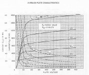
1) 35LR6 g2 curves $17
--
Re: payloadde
Yes, undocumented, and not on all 38HE7 tubes, but most I have seen. Not on 12HE7 at all. The pentode should be good for 15 Watts Pdiss without all that damper diode heat next to it.
--
It certainly is easier to do really low power output with the original LV tubes. But there is a large gap between the various tube technologies.
Space Charge tubes (12K5) are 10 mW to 40mW output, maybe 4X that in P-P. Rather non-linear curves, 10% dist. These are dissipating a Watt on g1 internally. Could these be run with "Crazy Drive" to linearize them and get maybe a Watt output? (Probably not worth the bother to find out)
26A7 looks like 0.44 Watts output in P-P, 5% dist. 16 Watt heater!
(This smells like a TV Sweep tube without any plate area. Look at the 6DQ5 datasheet for Vg2 = 25V, it works better!)
Some voltage regulator/control tubes like 7233, 6C33, 6AS7... can handle higher currents, but being triode, waste too much plate voltage.
Some of the TV Sweeps can work well with just 75V on g2, and only waste 30V on the plate V (knee). These could get you up to 100 Watts with 160V B+ using "Crazy Drive" and less than 1% dist. 26LX6 26DQ5 35LR6
26DQ5 could work with 50V on g2 for maybe 7 Watts out in P-P with 100V B+.
I don't see anything that outclasses a 26DQ5, 26LX6 or 35LR6. They can beat the LV tubes at LV, and can do reasonable power at 75V on g2, with 160V to 200V for B+. Crazy Drive can keep the distortion low with the necessary low Z primary OT.
http://frank.pocnet.net/sheets/137/1/12K5.pdf $8
http://frank.pocnet.net/sheets/049/2/26A7GT.pdf $7
http://frank.pocnet.net/sheets/142/7/7233.pdf $12
http://frank.pocnet.net/sheets/123/2/26LX6.pdf $21
http://frank.pocnet.net/sheets/106/6/6DQ5.pdf $3 26DQ5
1) 35LR6 g2 curves $17
--
Re: payloadde
Yes, undocumented, and not on all 38HE7 tubes, but most I have seen. Not on 12HE7 at all. The pentode should be good for 15 Watts Pdiss without all that damper diode heat next to it.
--
Attachments
Last edited:
One more super low knee voltage tube, the 6CB5A, it may be the best one.
(I would test them all, datasheets are sometimes optimistic compared to the real thing.)
12GE5 and 21LG6A are pretty good too.
http://frank.pocnet.net/sheets/137/6/6CB5.pdf $5
http://frank.pocnet.net/sheets/123/6/6GE5.pdf $3 12GE5
http://frank.pocnet.net/sheets/123/6/6LG6.pdf $4 21LG6A
(I would test them all, datasheets are sometimes optimistic compared to the real thing.)
12GE5 and 21LG6A are pretty good too.
http://frank.pocnet.net/sheets/137/6/6CB5.pdf $5
http://frank.pocnet.net/sheets/123/6/6GE5.pdf $3 12GE5
http://frank.pocnet.net/sheets/123/6/6LG6.pdf $4 21LG6A
This is nice! tubes that do lv better than lv![emoji4] .
The 26a7gt it seems (though I'm not sure) was usable in car audio and military radios.
Thanks smoking amp, for doing the exploration on our behalf!
Can I also ask what exactly the crazy drive is? Googling doesn't seem give any worthwhile results.
The 26a7gt it seems (though I'm not sure) was usable in car audio and military radios.
Thanks smoking amp, for doing the exploration on our behalf!
Can I also ask what exactly the crazy drive is? Googling doesn't seem give any worthwhile results.
Last edited:
@Jmfahey. Your mention of high voltages used back in the day reminds me of this episode of Fringe in which Walter Bishop, sitting in the Harvard campus smoking something, complains of how kids these days are so afraid of doing anything fun [emoji4] . I guess universities more so
https://youtu.be/5CbhF-yqzOA
Sent from my ASUS_Z00AD using Tapatalk
https://youtu.be/5CbhF-yqzOA
Sent from my ASUS_Z00AD using Tapatalk
Last edited:
IMO, that 40 V. university limit is ridiculous.  Everybody seems to be worried about legal liability and protecting people from their own stupidity. Life without risks is not possible. Part of a well balanced education is learning to manage risk.
If a student wanted to build a 200 WPC SS amp for class, that 40 V. rule blocks the desire. 200 WPC requires 40 VRMS be delivered to an 8 ohm load. Which means the theoretical minimum for the PSU is (sic) +/- 57 V. Real world conditions require those rails to be even "taller". That's right folks; a "sand" amp can do some serious damage to you, should proper caution not be exercised.
Fear and fire are good servants and very bad masters. Be the master!
Everybody seems to be worried about legal liability and protecting people from their own stupidity. Life without risks is not possible. Part of a well balanced education is learning to manage risk.If a student wanted to build a 200 WPC SS amp for class, that 40 V. rule blocks the desire. 200 WPC requires 40 VRMS be delivered to an 8 ohm load. Which means the theoretical minimum for the PSU is (sic) +/- 57 V. Real world conditions require those rails to be even "taller". That's right folks; a "sand" amp can do some serious damage to you, should proper caution not be exercised.
Fear and fire are good servants and very bad masters. Be the master!
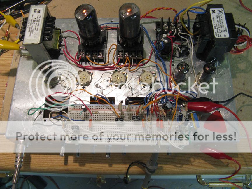
I checked the knee voltages for a few tubes on the curve tracer here.
The 26DQ5 came out best (least knee V).
For 70V on g2:
26DQ5 24V knee
6CB5 Sylvania square plate 32V knee
6CB5 Sylvania round plate 32V knee
6CB5 GE round plate 40V knee
6CB5 RCA 28V knee
35LR6 Sylv 40V knee
26LX6 Zenith 35V knee
However, 35LR6 and 26LX6 only need 40V on g2 to reach the same currents as the others. So for 40V on g2:
35LR6 28V knee
26LX6 28V knee
The 26A7GT is still doing better. For Vg2 = 26.5V is has a knee of 5V. That would put the Vg2=70 V knee around 12V probably.
http://frank.pocnet.net/sheets/049/2/26A7GT.pdf
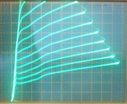
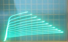
2 pics of the 26DQ5 with Vg2 = 70V, 20V/div Horiz., 1.1 V steps on g1
1) 20 mA/div Vert
2) 50 mA/div Vert
----
re: darksideboy
Crazy Drive is a variation on grid 2 drive, but with a resistor from grid2 to grid1, and another resistor from grid1 to cathode. Info and pics over here:
http://www.diyaudio.com/forums/tube...nificent-television-tubes-47.html#post4574362
Crazy Drive does increase the knee voltage some over g1 drive, but not by much. A volt or two for these low Vg2 levels.
--
The 26DQ5 came out best (least knee V).
For 70V on g2:
26DQ5 24V knee
6CB5 Sylvania square plate 32V knee
6CB5 Sylvania round plate 32V knee
6CB5 GE round plate 40V knee
6CB5 RCA 28V knee
35LR6 Sylv 40V knee
26LX6 Zenith 35V knee
However, 35LR6 and 26LX6 only need 40V on g2 to reach the same currents as the others. So for 40V on g2:
35LR6 28V knee
26LX6 28V knee
The 26A7GT is still doing better. For Vg2 = 26.5V is has a knee of 5V. That would put the Vg2=70 V knee around 12V probably.
http://frank.pocnet.net/sheets/049/2/26A7GT.pdf
2 pics of the 26DQ5 with Vg2 = 70V, 20V/div Horiz., 1.1 V steps on g1
1) 20 mA/div Vert
2) 50 mA/div Vert
----
re: darksideboy
Crazy Drive is a variation on grid 2 drive, but with a resistor from grid2 to grid1, and another resistor from grid1 to cathode. Info and pics over here:
http://www.diyaudio.com/forums/tube...nificent-television-tubes-47.html#post4574362
Crazy Drive does increase the knee voltage some over g1 drive, but not by much. A volt or two for these low Vg2 levels.
--
Attachments
Last edited:
Since the 26A7GT only has 40 mA at its 5V knee (Vg2 = 26.5V)
I tried the 26DQ5 at a 40 mA knee (Vg2 = 22V), and the knee V is 10V.
The 26DQ5 knee done earlier, with Vg2 = 70V, was at 215 mA with a 24V knee V
I tried a 12GE5 too, a 40 mA knee (Vg2 = 33V) gives a knee V of 13V.
12GE5 with Vg2 = 70V gives a 120 mA knee of 26V
Tried 35LR6 at a 40 mA knee (Vg2 = 16V) and the knee V is 9.5V
35LR6 with Vg2 = 70V gave a knee at 400 mA and 33V (the 40V listed earlier looks wrong)
Tried 21LG6 at a 40 mA knee (VG2 = 19V) and the knee V is 10V
21LG6 with Vg2=70V gave a knee at 250 mA and 29V
Tried 21HB5A at a 40 mA knee (Vg2 = 22V) and the knee V is 10.5V
21HB5A with Vg2 = 70V gave a knee at 183 mA and 28V
Tried 6HJ5 at 40 mA knee (Vg2 = 25V) and the knee V is 10.5V
6HJ5 with Vg2 = 70V gave a knee at 190 mA and 31V
Tried 38HE7 at 40 mA knee (VG2 = 26V) and the knee V is 10V
38HE7 with Vg2 = 70V gave a knee at 175 mA and 25V
Tried 26LX6 at 40 mA knee (VG2 = 14V) and the knee V is 9.5V
26LX6 with Vg2 = 70V gave a knee at 425 mA and 30V (the 35V listed earlier looks wrong)
(might be a scale calibration issue between 10V/div and 20V/div that changed the knee V for 35LR6 and 26LX6)
That's about all I have to add on LV tube amplifiers I guess. I'm not planning on building one.
You need like 200V B+ to make a decent amp (75 Watt out), but you could scrimp by on 120V I guess, with lowish power out (maybe 8 Watts) and low plate efficiency.
--
Last edited:
IMO, that 40 V. university limit is ridiculous.
If a student wanted to build a 200 WPC SS amp for class, that 40 V. rule blocks the desire. 200 WPC requires 40 VRMS be delivered to an 8 ohm load. Which means the theoretical minimum for the PSU is (sic) +/- 57 V. Real world conditions require those rails to be even "taller". That's right folks; a "sand" amp can do some serious damage to you, should proper caution not be exercised.
Fear and fire are good servants and very bad masters. Be the master!
Yes. At 40v, if you want to annoy the neighbors, you'll have to use sand.
And probably have to use a chip amp, potentially Class-D, though with efficient speakers, maybe an lm3886 or similar can rattle a window with a +/-20v supply.
Woops, correction.
That would be more like 40 or 50 Watt output with 200V B+ and the biggest Sweep tubes, using conservative ratings in class AB.
------------------------------
While 160V to 200V may not qualify as "SAFE" by most standards, you would most likely survive that, unless suffering a heart condition already, or having just stepped out of the shower. More typical 400V and up tube amp B+ might well be a different story.
I have a bunch of dual 155V switching supplies I got off Epay for cheap, and that's what I would normally use for an Amplifier (ie, 310V B+, 155V Vg2). Although the variable bench supplies go up to 600V.
Last edited:
Checked a GE 12HL7 at 40 mA, and the knee V is 17.5V (Vg2 = 75V)
then a Zenith (probably Sylvania) 12HL7 at 40 mA, and the knee V is 25V (Vg2 = 74V)
then a Sylvania 12HL7 at 40 mA, and the knee V is 18V (Vg2 = 73V)
then a GE 12GN7 at 40 mA, and the knee V is 22V (Vg2 = 75V)
a Sylvania 6HB6 at 40 mA, knee V 30V
a GE 6JC6 at 20 mA, knee V 32V (Vg2 = 114V)
a Raytheon 6JC6 at 20 mA, knee V 38V (Vg2 = 114V)
an RCA 6JC6 at 20 mA, knee V 37V (Vg2 = 114V)
an RCA 6EW6 at 20 mA, knee V 46V (Vg2 = 120V)
Looks like the small tubes are an even BIGGER problem for knee V.
Well, one would run at lower currents than tested here (like 1/4 these).
Taking the GE 6JC6 at 5 mA, the knee drops to 9V (Vg2 = 40V)
11HM7 at 10 mA, the knee is 12.5 V (Vg2 = 31V)
Taking the best GE 12HL7 at 10 mA, the knee drops to 7V (using 31V on Vg2)
Thats fine. 12HL7 or 6JC6 should work for the front end.
That 5963 triode in Mona Ketje's schematic has a 10 V loss running at less than a 1 mA.
Last edited:
You can get a decent enough performance and about 7watts of power out of a PP 6AS7 running off a 130V B+. The grid bias is about 30V so the driver requirements are not excessive and can be achieved with a 5687 LTP with a 2V input and a phase splitting input transformer.
The only fly in the ointment is that the stated mu of 2 is a killer. in real life applications you are unlikely to get more than unity gain from these valves which means that 2/3 of the potential output swing that is available from the B+ is unachievable due to grid bias restrictions.
The EL86 makes for a better low voltage candidate and a very good amp can be achieved with a 170-200V B+ supply.
I have also achieved good results from a PP QQV03-12 running at just 150V B+. Use a 12V SMPS for heaters and then a DC to DC converter to generate your +B and you can have a very cheap and very compact little amp with a potential output of about 5W (using 200V).
Shoog
While there's not much power, 3S4s are "happy" with 45 V. B+ and 90 V. is the top limit. Setting 3S4s up for PP near Class "B1" operation is "interesting". Lots of alkaline cells/batteries at work. Each 3S4 requires its own "floating" 3 VDC filament supply. Fortunately, alkaline "D" cells will last for a reasonable amount of time. Then there's the bias supply.
FWIW, several years ago I was helping somebody working with kids and 45 V. was the upper limit on B+, for safety reasons. 1U4s and 1S5s are the obvious candidates for voltage amplification. FETs in the "concertina" phase splitter role.
Have you seen the Bottlehead Quickie? Its a preamp using 3S4 tubes triode strapped with four 9v batteries in series for the B+ supply. Works really well as a pre, and its so simple and safe to work on i would recommend it to anybody who wants to get a taste for tubes.
I've slowly modified mine into an AC powered headphone amp with small output transformers, plate chokes, 75v gas regulator tube for the B+, and Rod coleman filament regulators. Really does sound wonderful, and its cute looking too 🙂
The GE 12HL7 is actually beating the 3S4 or 5963 for lowest knee voltage for a small signal tube. (7V versus 15V or 10V) And its got some real gm to operate it.
The 26DQ5, 35LR6 and 26LX6 are close contenders with the 26A7GT at 40 mA for knee voltage. At least they have -some- Pdiss available.
(10V, 9.5V and 9.5V versus 5V)
EL86 is essentially a TV Sweep pentode, the rounded pentode knee puts it up around 50V knee, where the beam pentode Sweep types are around half that.
http://frank.pocnet.net/sheets/137/3/3S4.pdf
http://frank.pocnet.net/sheets/049/2/26A7GT.pdf
http://frank.pocnet.net/sheets/010/e/EL86.pdf
So a modern LV tube amp would want a GE 12HL7 ($1, 10 W Pdiss) for input tube and a 26DQ5 ($3, 26 W Pdiss) for the output tubes in P-P. (38HE7 would be another possibility for output, no plate cap, 10V knee, 15 Watt $1)
With those in mind, one might put a switch on the bottom plate of the amplifier that switches to a low B+ whenever the cover is open, and to a high B+ when the cover is closed. (the Volkswagoner amplifier 😀 passes safety inspection!) Being pentodes, that should be possible without biasing changes, using some CCS devices for loads too.
One other approach would be to use ferrite switchmode impedance converters with the output tubes, in sealed boxes that the tubes plug in to. To the outside world, they would appear to be SS LV devices then.
Last edited:
"Volkswagoner amplifier"... Ha-ha... Nice one smoking amp.. Any way to measure the actual distortion values of 26a7gt? 5% sounds ridiculously unusable [emoji4]
Sent from my ASUS_Z00AD using Tapatalk
Sent from my ASUS_Z00AD using Tapatalk
There are techniques to analyse the spacing of plate curves on a load line to get distortion off the datasheet. (most tube textbooks) 5% dist. is actually not that high, the 6BQ5/EL84 can reach 10% in some configurations given on its data sheet:
http://frank.pocnet.net/sheets/093/6/6BQ5.pdf
You just need more gain in the feedback loop to clean it up then. But I would rather use something with low distortion to begin with. "Crazy Drive" looks like the ticket for using TV Sweep tubes with very low distortion. Its a modification of grid 2 drive, so low screen grid V tubes are the useful ones.
26A7GT might be able to use "Crazy Drive" to clean it up, but its 2 Watt Pdiss and 16 Watt heater leave a lot of room for improvement. I'll take the $3 24 Watt 26DQ5 over that.
It would be interesting to have such a "Volkswagoner" amplifier that could work on both LV or HV B+ for servicing purposes. Safe to work on, powerful and clean when operating. Quite a design challenge to get it to work both ways though.
@smoking-amp,
Would there be a schematic for the crazy drive? I could swear I understood it the last time I read, but now I'm more confused.
From what I understand, crazy drive since signal is also applied to grid2, both grid 1 and grid 2 act like grids instead of grid 2 acting as it does.
Sent from my ASUS_Z00AD using Tapatalk
There was a 4D32 SE amp that AJT posted in that link to Crazy Drive which had it on the 4D32. It's just voltage drive of grid2, with a resistor from grid2 down to grid1, then another resistor from grid1 to cathode. They get tweeked for best linearity. A bunch of the common Sweep tubes were eventually posted with representative resistor values in that thread. Both grids are controlling together, so the drive signal required is less than grid 2 drive alone. Grid 1 is largely current driven however, while grid 2 is voltage driven (but consuming current as well).
You need a Mosfet (or cathode ) follower to drive grid2, since it draws some current. Tube biasing typically done on the gate side of the Mosfet then. The driver tube needs to be able to deliver about a 60 V swing, up to a 150V swing, depending on the output tube (for TV Sweep tubes) and operating power level. Audio type tubes would require significantly more drive signal due to 250V grid 2 operation typically.
Crazy Drive can be used for SE as well as P-P. It has high output Z though, like g2 drive or a normal pentode. So some kind of local Fdbk is needed to lower that.
Last edited:
@smoking-amp,
Would there be a schematic for the crazy drive? I could swear I understood it the last time I read, but now I'm more confused.
From what I understand, crazy drive since signal is also applied to grid2, both grid 1 and grid 2 act like grids instead of grid 2 acting as it does.
Sent from my ASUS_Z00AD using Tapatalk
Something like this maybe (not my circuit, just found on the net):
12GB7 is a typical Japanese TV sweep tube.
Attachments
- Status
- Not open for further replies.
- Home
- Amplifiers
- Tubes / Valves
- "Low" B+ Voltage Amplifiers