Thanks folks, this is very educational. I see that power stage is directly coupled with the driver. is this the property of the design or is it there just so that the grid1 and grid 2 are positive ?
Sent from my ASUS_Z00AD using Tapatalk
Sent from my ASUS_Z00AD using Tapatalk
12AX7. Yes, indeed, as a power tube. Class B zero bias at 50-100V. About 1kohm input resistance, 4kohm load, 1W per tube.
Tim
Tim
Yes, both grids are pulled positive, although g1 only a small amount. (it only draws a few mA)
It is puzzling to see another schematic with this configuration, since word doesn't seem to have ever gotten around about this approach. Also, the 14K and 10K resistor chain is much higher value than what I have found to give linearization on the curve tracer. Typically more like 1K or 2K range.
The earlier 4D32 was an odd HV zero bias tube (with similar high value resistors used for the grids on the schematic), which I did not have a sample to test. But the Hitachi 12G-B7 looks like an ordinary TV Sweep tube, except high gm. So it is not clear these schematics were being optimised for the linearity function, maybe just as a booster for drive sensitivity. Maybe I can get one to test.
http://www.shinjo.info/frank/sheets/133/1/12G-B7.pdf
Last edited:
I just wanted to draw peoples attention to this DC to DC converter which should make an excellent cheap candidate for a HV supply for these projects.
150W Inverter Battery DC 12V to DC 220V Voltage Step Up Boost Converter Module | eBay
I have just ordered one along with a 12V SMPS to get a project back on the road.
I think, given the ridiculous price that transformers have risen to, this is the way forward for many introductory projects, especially considering the savings to be made in HV capacitors as well.
Shoog
Last edited:
I just wanted to draw peoples attention to this DC to DC converter which should make an excellent cheap candidate for a HV supply for these projects.
150W Inverter Battery DC 12V to DC 220V Voltage Step Up Boost Converter Module | eBay
Eww...
Tim
It says it's a DC to DC boost converter, so it's likely NOT isolated, but probably regulated.
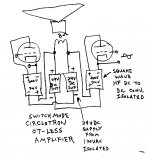
If someone made a square wave, ISOLATED converter (and un-regulated), one could use it as an impedance converter down to LV audio. Or another use would be just floating them at the plate cap of the tube. Then everything else could be ground based (including the OT) for improved safety. HV AC audio voltage swing would still be present obviously. Also could be used with a Circlotron Amp then too.
If someone made a square wave, ISOLATED converter (and un-regulated), one could use it as an impedance converter down to LV audio. Or another use would be just floating them at the plate cap of the tube. Then everything else could be ground based (including the OT) for improved safety. HV AC audio voltage swing would still be present obviously. Also could be used with a Circlotron Amp then too.
Right - more than likely not isolated.
They do make square wave isolated converters. One of the options discussed in the tosche station thread i started is to cannibalize a very cheap 220v inverter. Less than $15 shipped from aliexpress vendors. 12v input, vibrator, transformer. And some parts that try to shape the output so it looks more like mains AC. Just add rectifier.
.:Sent by pneumatic tubes
The isolation comes from the 12V SMPS you need to drive it, so isolation isn't a problem.It says it's a DC to DC boost converter, so it's likely NOT isolated, but probably regulated.
If someone made a square wave, ISOLATED converter (and un-regulated), one could use it as an impedance converter down to LV audio. Or another use would be just floating them at the plate cap of the tube. Then everything else could be ground based (including the OT) for improved safety. HV AC audio voltage swing would still be present obviously. Also could be used with a Circlotron Amp then too.
The SMPS can be used to drive the heaters so you get a whole regulated power supply with DC heaters for $25.00.
Shoog
If one had a simple HF square wave converter, DC to HV DC isolating, then one could do this below. The HV part could be kept to a small box around the converter with a tube socket for the tube to plug in. Everything else is LV. The front end of the amp could be LV tubes as considered earlier. This not only makes it practical to make a LV tube amp with decent power, but cheap too. It's a Circlotron configuration with ferrite impedance converters and switched mode power supplies.
Attachments
It says it's a DC to DC boost converter, so it's likely NOT isolated, but probably regulated.
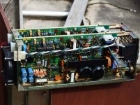
It is isolated.
It isn't regulated, or I hope not.
It's one of those retarded push-pull converters, commonly seen in automotive AC inverters.
It actually seems to have current limiting (a serpentine shunt resistor), at least. But the SG3525 is not a current mode controller. And critically, there is no filter inductor, neither primary nor secondary, so there can be no PWM regulation.
It's not a PWM controller, it's a charge pump.
The only reason these sorts of things even start once, is because they are made with a very slow soft starting time constant (probably the small electrolytic). During soft start, the lost energy is burned in transistor switching and avalanche.
If the load is heavy, or faulted, the transistors simply catch fire.
It may be "current protected", using the shunt resistor. There is mention of a latching protection.
When they say "150W", mind that that's the boundary where it catches fire at 25C ambient.
Tim
The sort of situation in which I envisage these been used will have a power draw much below 150W (in my case about 50W). There are quite a few designs out there which limit the power draw to just 40W (with peaks of 70W) so this design has a large margin over that.It is isolated.
It isn't regulated, or I hope not.
It's one of those retarded push-pull converters, commonly seen in automotive AC inverters.
It actually seems to have current limiting (a serpentine shunt resistor), at least. But the SG3525 is not a current mode controller. And critically, there is no filter inductor, neither primary nor secondary, so there can be no PWM regulation.
It's not a PWM controller, it's a charge pump.
The only reason these sorts of things even start once, is because they are made with a very slow soft starting time constant (probably the small electrolytic). During soft start, the lost energy is burned in transistor switching and avalanche.
If the load is heavy, or faulted, the transistors simply catch fire.
It may be "current protected", using the shunt resistor. There is mention of a latching protection.
When they say "150W", mind that that's the boundary where it catches fire at 25C ambient.
Tim
I am just going to have to see if they work out as hoped when they arrive in about 3 weeks time.
Shoog
I'm wondering if any of you have spotted a switching power supply on ebay i.e. with B+ & filament etc? Can't find any...
I'm wondering if any of you have spotted a switching power supply on ebay i.e. with B+ & filament etc? Can't find any...
They don't appear to exist as commercial products. Someone did develop one with all the necessary outputs back in 2012 and they were discussed on these boards with the potential to become commercially available - but they obviously never took off.
If there is a simple B+ SMPS out there it is not offered through Ebay and is likely to be much more pricey as a consequence.
The only option I have seen is to use a 12V SMPS to drive one of these DC to DC converters. There are a few different modules available, but most seem fairly limited in power output (40W). There is a Pulse Width Modulation module that is rated at 100W running at 20khz but it needs rectification and filtering before it offers B+ potential.
Shoog
Well there are SOME switching power supplies on Ebay that will do HV, but $$$$$$
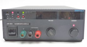
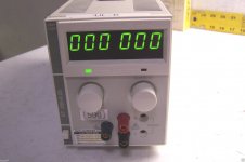
Xantrex XHR-600 around $1000 lately (used to be able to get a broken one for $50 to $100). Or a Xantrex XT-250, you can find them for $120 occasionally, twice that if you are in a hurry.
And I found some Xantrex custom made power supplies, 2 x 155V, 2x300 Watt, made for Nasa. These were just $30, but I found them years ago.
Attachments

Shoog said:The EL86 makes for a better low voltage candidate and a very good amp can be achieved with a 170-200V B+ supply.
Now a push-pull EL86 amp is something I'd be interested in. What kind of driver is needed?
I have a couple of 5k:VC OPT's that don't lend themselves to inexpensive tubes (can't use EL84 or 6V6, for instance). But I think they'd work for EL86 or 6P43P.
--
My go to valve is a 6AU6 (because Schade needs a pentode) but I daresay the 5687 would make an excellent candidate.Now a push-pull EL86 amp is something I'd be interested in. What kind of driver is needed?
I have a couple of 5k:VC OPT's that don't lend themselves to inexpensive tubes (can't use EL84 or 6V6, for instance). But I think they'd work for EL86 or 6P43P.
--
Shoog
My go to valve is a 6AU6 (because Schade needs a pentode) but I daresay the 5687 would make an excellent candidate.
5687 as a cathodyne, you think? The bias on an EL86 (or 6P43P-E, in my case) with 250 plate volts would be about -20V or so, right?
I should look into doing a straight up LTP from two 6AU6 into a PP pair of EL86 pentodes into 5k:VC.
I think I have a decent circuit proposal using a 6DJ8 cathodyne into PPP 6P15P-triodes into a Dyna A470 OPT (roughly 4.5k to 5k primary).
Sorry about taking this a bit off from the topic of discussion which was switched power supplies folks, how would I run crazy drive in push pull configuration? I mean usually grid 2 is connected to the some tap of the transformer (ul?). What would it be in case of crazy drive? Or would ct be set to positive b+?
Sorry if this sounds a bit of a premature question. I am reading everything i find around the topic even as I ask this
Sent from my ASUS_Z00AD using Tapatalk
Sorry if this sounds a bit of a premature question. I am reading everything i find around the topic even as I ask this
Sent from my ASUS_Z00AD using Tapatalk
Last edited:
Imagine a mirror image of the above schematic (with a push-pull output transformer). Of course, you will need to add a phase inverter as well.how would I run crazy drive in push pull configuration?
Last edited:
- Status
- Not open for further replies.
- Home
- Amplifiers
- Tubes / Valves
- "Low" B+ Voltage Amplifiers