In this thread, a suggestion was made that a new thread be started on reasonably low B+ voltage amps. Here it is. 😉
Aside from the thread linked above, I suggest that members hop over to AA and check out a thread, where Jeff Yourison and I worked on PP 6Y6 setup. Tom Bavis provided a crucial suggestion that finally settled things down.
Obviously, more ideas will be mentioned in subsequent posts.
Aside from the thread linked above, I suggest that members hop over to AA and check out a thread, where Jeff Yourison and I worked on PP 6Y6 setup. Tom Bavis provided a crucial suggestion that finally settled things down.
Obviously, more ideas will be mentioned in subsequent posts.
I guess the idea would be what would be safe for a complete novice to undertake as DIY. Certainly a bit of wobble room there.
Some key items I think would be high gm (like frame grid) tubes, so as to get some current at low voltage. High current capable tubes for the output would be highly useful for keeping the B+ down. Here again, the required output power level is a big unknown, so solutions could be wide ranging. The availability of the low primary Z Edcor CXPP25-8-1.6K would seem a good starting point for low B+. There is also an Edcor GXPP15-8-1.7K. And no plate caps on the tubes, for safety. A PCB (printed circuit board) for foolproof construction of course.
( copied over my comments in the other thread: )
Looking through some tube datasheets, I see a simple approach that could be done cheaply, based on a modification of Pete Millett's DCPP amplifier. Which is just a differential front end, with TV tube P-P finals. Lets say 160V B+, which is conveniently available from a cheap 120VAC:120VAC industrial isolation xfmr.
The front end could be 6EW6, 6JC6 or 12HL7 tubes. (12HL7 for driving bigger output tubes like 6HJ5) These are all in the $3 or $4 dollar range. (12HL7 only $1 on sale lately) The output tubes must be plate cap-less and capable of LV high current operation. This would call for a low Zprimary OT, and Edcor has just such an animal, the CXPP25-8-1.6K for $52. Normally low Zprimary would lead to high distortion with small Watt tubes, but the recent "discovery" of "Crazy Drive" allows for a perfect match. Tubes such as 12GE5 (a 6JN6 equivalent), at $3, or 6HJ5, at $4, would fit the bill. Or say 21HB5 (no cap, bigger than 12GE5) or 13GB5 (cheap, but has a cap).
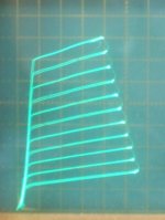
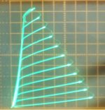
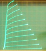
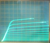
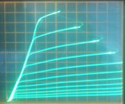
The "Crazy Drive" curves below for the 12GE5 and 6HJ5 show why a low Z primary will work just fine for low distortion here. Only 60V of drive from the front end are required to reach almost 150 mA from the 12GE5 tubes. 6HJ5 is similar, but bigger Watts, and can develop 450 mA with 75V of drive. The "Crazy Drive" curves are so linear, that almost ANY load line gives linear results. The 6HJ5 would likely max out the CXPP25-8-1.6K OT using 150V B+. Mosfet followers, or "Power Drive", would be needed to drive the final output screen grids.
One could try Schade "local" feedbacks (like in the original DCPP Amp) to lower the output Z for good damping factor, but likely will need to use plate to driver cathode or driver screen grid (crossed) Fdbks here. (due to 3X lower loop gain around just the final tube with Crazy Drive) 12HL7 are so linear Mu-wise between g2 and g1, that feedback to the g2 would be fine if sufficiently low output Z can be obtained that way. (and no Fdbk caps are needed for the plate to g2 Fdbks)
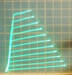
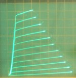
Crazy Drive curves, 50 mA/div Vert., 50V/div Horiz.
1) 12GE5 (probably 20 mA/div Vert shown here)
2) 6HJ5
3) 21HB5A
4) 13GB5 (has a plate cap)
Some key items I think would be high gm (like frame grid) tubes, so as to get some current at low voltage. High current capable tubes for the output would be highly useful for keeping the B+ down. Here again, the required output power level is a big unknown, so solutions could be wide ranging. The availability of the low primary Z Edcor CXPP25-8-1.6K would seem a good starting point for low B+. There is also an Edcor GXPP15-8-1.7K. And no plate caps on the tubes, for safety. A PCB (printed circuit board) for foolproof construction of course.
( copied over my comments in the other thread: )
Looking through some tube datasheets, I see a simple approach that could be done cheaply, based on a modification of Pete Millett's DCPP amplifier. Which is just a differential front end, with TV tube P-P finals. Lets say 160V B+, which is conveniently available from a cheap 120VAC:120VAC industrial isolation xfmr.
The front end could be 6EW6, 6JC6 or 12HL7 tubes. (12HL7 for driving bigger output tubes like 6HJ5) These are all in the $3 or $4 dollar range. (12HL7 only $1 on sale lately) The output tubes must be plate cap-less and capable of LV high current operation. This would call for a low Zprimary OT, and Edcor has just such an animal, the CXPP25-8-1.6K for $52. Normally low Zprimary would lead to high distortion with small Watt tubes, but the recent "discovery" of "Crazy Drive" allows for a perfect match. Tubes such as 12GE5 (a 6JN6 equivalent), at $3, or 6HJ5, at $4, would fit the bill. Or say 21HB5 (no cap, bigger than 12GE5) or 13GB5 (cheap, but has a cap).
The "Crazy Drive" curves below for the 12GE5 and 6HJ5 show why a low Z primary will work just fine for low distortion here. Only 60V of drive from the front end are required to reach almost 150 mA from the 12GE5 tubes. 6HJ5 is similar, but bigger Watts, and can develop 450 mA with 75V of drive. The "Crazy Drive" curves are so linear, that almost ANY load line gives linear results. The 6HJ5 would likely max out the CXPP25-8-1.6K OT using 150V B+. Mosfet followers, or "Power Drive", would be needed to drive the final output screen grids.
One could try Schade "local" feedbacks (like in the original DCPP Amp) to lower the output Z for good damping factor, but likely will need to use plate to driver cathode or driver screen grid (crossed) Fdbks here. (due to 3X lower loop gain around just the final tube with Crazy Drive) 12HL7 are so linear Mu-wise between g2 and g1, that feedback to the g2 would be fine if sufficiently low output Z can be obtained that way. (and no Fdbk caps are needed for the plate to g2 Fdbks)
Crazy Drive curves, 50 mA/div Vert., 50V/div Horiz.
1) 12GE5 (probably 20 mA/div Vert shown here)
2) 6HJ5
3) 21HB5A
4) 13GB5 (has a plate cap)
Attachments
Last edited:
Or 100 V B+ with a dozen 12HL7 in parallel. (Fewer tubes needed with higher B+)
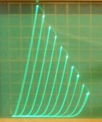
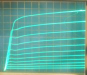
gm = 240000 for a dozen of them. Just need a splitter in front. Triode mode is probably out for low B+ operation, too much voltage eaten up by the tube before any current flows.
1) 12HL7 in triode mode
2) 12HL7 in "Crazy Drive" mode
gm = 240000 for a dozen of them. Just need a splitter in front. Triode mode is probably out for low B+ operation, too much voltage eaten up by the tube before any current flows.
1) 12HL7 in triode mode
2) 12HL7 in "Crazy Drive" mode
Attachments
Last edited:
Hmmm, I see Edcor has a low primary Z SE OT too, GXSE15-8-1.7K.
SE would keep things really simple, less chance of mistakes, useful for a point to point wired DIY Amp at least. But likely output power challenged. Could just use a bank of 12HL7 in parallel to drive that. Probably don't even need a voltage stage in front of that for grid 1 drive.
However, one would need a voltage stage in front to use "Crazy Drive", for LINEARITY with such a low primary Z OT. And the input stage is needed for a Fdbk loop to lower the output Z for damping.
Hmmm, maybe could use + and - supplies to get more total B+ for an amplifier design, and keep each polarity to one side of the PCB board. (parts placed on both sides according to voltage?) So eliminate the chance of getting a zinger across both supplies at once. Yeah, that would allow a vastly larger realm of designs, almost back to standard ones....
I guess I'm out of ideas beyond that. Put Mosfets in glass tubes.
Last edited:
One more wild idea:
The old space charge tubes for car radios of course were low voltage, but they were not very HiFI. However, "Crazy Drive" is somewhat similar in operation to those, using positive g1, except using a variable current fed g1. Maybe "Crazy Drive" could work with the old space charge tubes linearly? Unfortunately I don't have any here to try on the curve tracer. I may order a few if they are still available. That might get us down to a +12V or +24V operation level, but low power. Can always parallel them. Probably could use a power toroid for an OT, or an old transistor radio output xfmr.
The old space charge tubes for car radios of course were low voltage, but they were not very HiFI. However, "Crazy Drive" is somewhat similar in operation to those, using positive g1, except using a variable current fed g1. Maybe "Crazy Drive" could work with the old space charge tubes linearly? Unfortunately I don't have any here to try on the curve tracer. I may order a few if they are still available. That might get us down to a +12V or +24V operation level, but low power. Can always parallel them. Probably could use a power toroid for an OT, or an old transistor radio output xfmr.
Last edited:
While there's not much power, 3S4s are "happy" with 45 V. B+ and 90 V. is the top limit. Setting 3S4s up for PP near Class "B1" operation is "interesting". Lots of alkaline cells/batteries at work. Each 3S4 requires its own "floating" 3 VDC filament supply. Fortunately, alkaline "D" cells will last for a reasonable amount of time. Then there's the bias supply.
FWIW, several years ago I was helping somebody working with kids and 45 V. was the upper limit on B+, for safety reasons. 1U4s and 1S5s are the obvious candidates for voltage amplification. FETs in the "concertina" phase splitter role.
FWIW, several years ago I was helping somebody working with kids and 45 V. was the upper limit on B+, for safety reasons. 1U4s and 1S5s are the obvious candidates for voltage amplification. FETs in the "concertina" phase splitter role.
Now you are talking... The schematic shown in the original post is hardly a "low" voltage design."happy" with 45 V. B+ and 90 V. is the top limit.

plate caps are ok - no more dangerous than any other termination. To me, the low voltage circuits should not be a proxy for "Safe for under-5's". It should be a "less likely to be lethal" training ground for safe build and diagnosis techniques. In which case, the plate / anode top cap is taught as being safe ONLY once its under a secure pokey-finger proof cover.
Re: Mona Ketje
That 26A7GT (2W dual pentode) has got some gm at least, 5700 at 20 mA. Can't say that much for most of the other LV tubes I've found, except for maybe 6GM8/ECC86. But the heater power is out of sight. Equivalent to 2.5 Amp at 6.3V ! Looks like about 0.44 Watts output from the Amp in P-P.
The $1 12HL7 offers 20,000 gm at 20 mA (10 W frame grid pentode), and can reach the 44 mA peak with about 75V on g2. It only uses 0.3 Amps at 12.6V for the heater. So I think we would want to substitute two of them for outputs there. 75V plate V would also bring the power output up to about 1/2 Watt.
Another output tube option might be 7233. gm = 17500 at 120 mA, but just 50V needed. 8 Watt Pdiss, Mu of 4.
The 5963 gets 3200 gm at 8.5 mA and 67.5V.
We could sub the $1 6JC6A ( 3.1 W frame grid pentode) with 16000 gm at 14 mA, which gets about 10 mA with 50V on g2 or 15 mA with 75V on g2. Internal Mu of about 60. Or just use it as a pentode.
But to get 25 Watts output at relatively LV (160V) for the CXPP25-8-1.6K OT, I think we would want to use the 6JC6A or 12HL7 as an input tube to a 12GE5 or 6HJ5.
http://frank.pocnet.net/sheets/123/6/6GE5.pdf (350 mA at 150V on g2, 12GE5 $3)
http://frank.pocnet.net/sheets/084/6/6HJ5.pdf (400 mA at 110V on g2, 6HJ5 $4)
http://frank.pocnet.net/sheets/123/2/21HB5A.pdf (450 mA at 130V on g2, $6 )
http://frank.pocnet.net/sheets/123/3/38HE7.pdf (450 mA at 130V on g2, $1 tube, $0.35 in quantity, can run the pentode only with 21V across pins 10 and 12 for heater)
---
Last edited:
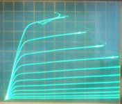
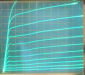
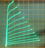
For those who are looking for a 50V (or 48V) B+ amplifier, I ran off some g1 drive plate curves for some likely (and mostly cheap) TV Sweeps at Vg2 = 48V. I figure plate caps are no longer an issue at +48V.
Things to look for are max current available (with 48Vg2) and how close the knees keep to the Vp = 0 border (left side) (Note: the higher current scale ones will look worse for knee V, but may not actually be different for the same current level)
All at 48V for g2, and 10V/div Horiz.
1) 12GE5 1V steps 10 mA/div Vert.
2) 6HJ5 1.5V steps 20 mA/div Vert.
3) 21HB5A 1V steps 20 mA/div Vert.
4) 38HE7 1V steps 10 mA/div Vert. (g1 = 0 curve goes up off the screen, just knee visible)
5) 21LG6A 1.5V steps 20 mA/div Vert.
6) 35LR6 1.2V steps 50 mA/div Vert.
7) 26DQ5 1.1V steps 20 mA/div Vert.
The last three: 5,6,7 have plate caps.
35LR6 looks like the winner for current, but it's the most expensive by far. (shown at 50 mA/div scale) (gm 16000)
26DQ5 looks good for keeping the knees at low V ($3 tube)
Attachments
-
 rsz_26dq5_g1_11vs_20ma_10v_48vg2.jpg89.7 KB · Views: 75
 -
 rsz_35lr6_g1_12vs_50ma_10v_48vg2.jpg92.3 KB · Views: 77
 -
 rsz_21lg6a_g1_15vs_20ma_10v_48vg2.jpg90.2 KB · Views: 455
 -
 rsz_38he7_g1_1vs_10ma_10v_48vg2.jpg87.9 KB · Views: 450
 -
 rsz_21hb5a_g1_1vs_20ma_10v_48vg2.jpg88.5 KB · Views: 453
 -
 rsz_6hj5_g1_15vs_20ma_10v_48vg2.jpg95.4 KB · Views: 464
 -
 rsz_12ge5_g1_1vs_10ma_10v_48vg2.jpg93.3 KB · Views: 484
Last edited:
Well, looks like you could only get a few Watts out using 48V with a 35LR6, even less with the others. Obviously, one has to go to positive grid drive at such low B+.
Tried the 26DQ5 and the knee moves up to 200 mA with +2.8V on g1 (from 130 mA at Vg1 = 0 ). But g1 starts consuming the extra current above that. 250 mA seems to be the max.
Tried the 35LR6 and the knee moves up to 315 mA with +1.5V on g1 (from 250 mA at Vg1 = 0 ). g1 starts consuming the extra current above that. 425 mA seems to be the max. This is only going to make 8 Watts at best in P-P.
OK, forget 48V.
B+ is going to have to be at least +100V. Looks like that would allow about 12X the Watts output from the datasheet. That puts us in the range for the CXPP25 or GXPP15 OTs then, depending on the tube used.
Maybe go for +/- 50V supplies to get that. B+ on one side of the PCB, and B- on the other side.
--
Last edited:
Then *forget* tubes, at least real ones used for real tube power.I guess the idea would be what would be safe for a complete novice to undertake as DIY.
Lower practical limit 160V which should allow for some tube power is still DEADLY , 100V which is practically useless is still so.
Any less and tube becomes just a glorified orange pilot light.
Old low voltage "radio tubes" are unobtanium and only live in yellowing Tube manual pages, definitely on no dealer shelves.
This reminds me of a guy who once suggested "safe" cartridges loaded with just a pinch of powder, "to keep bullets at safe air gun velocities"
He should have been reminded that even air guns can kill.
Well, a 100V to 160V B+ Tube Amp is indeed a tough challenge with conventional grid 1 drive circuitry and "audio" tubes, due to linearity problems and power limitations. With "Crazy Drive", frame grid tubes, TV Sweep tubes, and a low Z OT, 100V to 160V can be made to work well and linearly, it just needs enough for the screen grids to function sufficiently.
We just need to go with a split supply, and keep + and - on opposite sides of the PCB. Now agreed, that won't be safe if one puts wet hands into the thing. But, keep in mind that many SS Amps have +/- 50V to +/- 75V supplies too. So we are in the same ballpark at least. One could even epoxy over the PCB feed-through's that have opposite side potentials (components sorted to PCB sides as well, dependent on polarity association), so 50V would be the max exposure to careless hands.
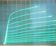
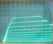
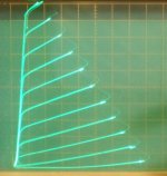
Call it an exercise. We HAVE the technology now. Once it is PROVEN, it will be copied abundantly. I wouldn't be a bit surprised if Crazy Drive, using +/- 75V power, and unilateralized "local" feedbacks, plus conventional/limited global Fdbk, could outclass ANY classic or current tube Amp. But sure, one would prefer to have +450V to do that.
Same tube:
1) new technology
2) old grid1 technology
We just need to go with a split supply, and keep + and - on opposite sides of the PCB. Now agreed, that won't be safe if one puts wet hands into the thing. But, keep in mind that many SS Amps have +/- 50V to +/- 75V supplies too. So we are in the same ballpark at least. One could even epoxy over the PCB feed-through's that have opposite side potentials (components sorted to PCB sides as well, dependent on polarity association), so 50V would be the max exposure to careless hands.
Call it an exercise. We HAVE the technology now. Once it is PROVEN, it will be copied abundantly. I wouldn't be a bit surprised if Crazy Drive, using +/- 75V power, and unilateralized "local" feedbacks, plus conventional/limited global Fdbk, could outclass ANY classic or current tube Amp. But sure, one would prefer to have +450V to do that.
Same tube:
1) new technology
2) old grid1 technology
Attachments
Last edited:
Old low voltage "radio tubes" are unobtanium and only live in yellowing Tube manual pages, definitely on no dealer shelves.
Whether or not stock is actually on the shelf is an unanswered question. However, RES has a $3 listing for 3S4s.
AES has a $3.34 listing for 3S4s and the indication is that stock is on hand.
Scarce? Sure, but still available.
I see the 5963 listed for $5, and the 26A7GT listed for $7 at Vacuumtubes.net
But those tubes in sequence can only get one one up to 0.44 Watts output. 3S4 similarly, about 0.4 W in PP.
The Edcor CXPP25-8-1.6K OT would require about +200V B+ to get 25 Watts out using some Sweep tubes. The GXPP15-8-1.7K OT would require about 165V B+ to get 15 Watts out. The GXPP10-8-1.7K would require about 150V B+ to get 10 Watts out. (allowing for 60V minimum tube conduction in all cases)
Using just 100V B+ on the GXPP10-8-1.7K would only give about 2.9 Watts out. One needs more like a 600 Ohm OT to use 100V B+ with Sweep tubes for 15 Watts out. Nothing like that at Edcor (except as a secondary Z).
There is GXPP15-16-1.7K (and GXPP10-16-1.7K) which could be used with an 8 Ohm load to get an 850 Ohm primary. They would be good for 70% of their power ratings, so 10 Watts and 7 Watts. (and that would lower the bottom freq. response to 28 Hz too) Would take about 125V B+ to get 10 Watts out of the GXPP15-16-1.7K that way. And about 115V B+ to get 7 Watts out of the GXPP10-16-1.7K similarly.
Their is no CXPP25-16-1.6K, but one likely could request one as custom. It would be good for 17.6 Watts then with the 8 Ohm load. And good down to 14 Hz.
Well, to get any decent tube efficiency, will require 200V for B+. Otherwise, make the 3S4 or whatever tube into a Darlington with a Mosfet or Bipolar transistor.
The 12HL7 would require 150V on g2 to get 100 mA max knee (which is 2X the 50 ma max DC rating).
Then one needs like 10 12HL7 in parallel to equal a TV Sweep tube.
And the 6JC6 would similarly require 125V on g2 to get 27.5 mA max knee.
Those would seem to set practical B+ minimums.
---
Last edited:
Come to think of it, these TV type tubes were all designed to run off about 160V in the TV set, with some allowance for power line brownout.
I would then need another 30V above that for a CCS load on the driver tubes for driving the Sweep tube g2 grids (through Mosfet followers). So everything seems to want 200V B+. (at least 160V) I guess one can't beat that 200V B+ figure, unless you can settle for milliWatts from battery tubes. But 200V B+ WILL get one up to 100 Watt output with big Sweeps at least, if needed. And there are OTs off the shelf for 10 Watt to 100 Watt that will work with them.
Of course, higher B+ yet will get you higher power and improved plate efficiency.
Last edited:
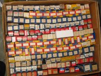
Old low voltage "radio tubes" are unobtanium and only live in yellowing Tube manual pages, definitely on no dealer shelves.
Maybe where you live, but there are places that are massively loaded with tubes.
Like these in my garage.
One of many boxes, this one has the little battery-radio types
Attachments
Brilliant thread. Especially for newbies. Thanks folks. I know space charge tubes have been already mentioned but I was wondering how much distortion would the space charge phenomenon introduce - especially compared to the distortion admitted by low impedance transformers? I ask this especially because they seem to have particularly simple circiluits. The 26A7gt is a specially unique tube. Also l, since transformers - even custom ones - is still pretty easy to find, maybe custom transformers can be recommended (and even be instructiinal). Also, would our options increasr if we accept lower power requirements, like say 5 to 8 Watts which can drive sufficiently high sensitivity speakers well.
Sent from my ASUS_Z00AD using Tapatalk
Sent from my ASUS_Z00AD using Tapatalk
- Status
- Not open for further replies.
- Home
- Amplifiers
- Tubes / Valves
- "Low" B+ Voltage Amplifiers