Hi,
I spent a lot of time reading posts on this forum and eventually decided to build segmented wire stator ESL. It's amazing how much knowledge is stored here. It can be easily turned into ESL building bible. I 'd like to thank everyone who contributed here and I would greatly appreciate any input and critique of my design.
I want to build panels that can be crossed with dipole subs or open baffle woofers (TBD).
My objectives for the panels are:
1. flat (+-2db) in 0.1-16KHz range
2. efficiency > 84 db
3. decent CSD
4. impedance > 3Ohm, min 1 Ohm.
I'm planning to stack two 12”x 35.4” (emitting area) segmented wire panels.
Design parameters:
Open area 42%,
11 electrical segments in symmetrical configuration with double width central segment.
D/S= 2.5mm,
FL = 100Hz,
Vbias = 6 kV.
Panel construction.
I considered two types of stators : ladder /lattice and louver. Lattice type calls for the use of HPL. The advantages of HPL are remarkable structural stability and high resistivity. It seems 0.187” sheet can be used to build the lattice. On the downside it is difficult to machine HPL and to maintain D/S variation < 10%.
Another option is to use 1/4” HPL sheet for the frame and 1/8 galvanized aluminum for crossbars. While cutting to length and galvanizing Al is not a difficult task, cutting groves in HPL with depth accuracy better than 0.25 mm is a challenge.
I'm leaning towards using 3/8” acrylic louvers with 22 AWG PVC insulated wires which will be stretched 1% on pin jig. I want to glue 115 wires to the louver using E6000 adhesive and divide them in 21 (w=11.1mm) segments.I'm planning to use 4 horizontal spacers per panel with the distance between spacers 22 cm.
6 mkm Mylar-C will be stretched 1% along its length, heat treated to mitigate relaxation effect and attached to the stators with VHB foam tape. I'm planning to use carbon tape for contacts.
Electronics:
Bias supply: 12V DC -> LM2596 DC-DC step down converter-> CXA LTL10 HV converter-> 5 stage voltage multiplier.
Voltage multiplier:
current limiting resistor 1 kohm, load resistor 20 Mohm,
ceramic capacitors 470pF 2kV,
diodes 2A,2kV (2 series diodes per stage).
Step up transformers:
4 Vigortronix VTX-146-050-106 230V Single Primary 50VA 0-6V
Thanks.
Alex
Last edited:
Welcome to club of building ESL's 🙂.
I am not entirely sure from you description, are you looking to build full range ESL's or a "hybrid"?
I am not entirely sure from you description, are you looking to build full range ESL's or a "hybrid"?
Welcome to club of building ESL's 🙂.
Thanks.
I am not entirely sure from you description, are you looking to build full range ESL's or a "hybrid"?
It’s a good question and I don’t have a definite answer. Depending on the diaphragm resonance which I can try to tune I can probably get a decent response down to 60Hz. However I don’t think I can run VTX-146-050-106 transformers below 100Hz.
Full range ESL's are a different animal.... I initially wanted to do a full range but decided against it for my 1st build. They have more complexities, the transformer is just one of them.
Research long and hard before you dive into full rangers.... there is a reason commercial makers go with hybrids 🙂.
Research long and hard before you dive into full rangers.... there is a reason commercial makers go with hybrids 🙂.
If you can find good step up transformers, full range can be very nice, IMO.
The only full range transformers that I found so far are M399 ESL step-up transformers 125:1 turns ratio, 2.5" M6 core, can be run down to 75 Hz and rated at 4500 volts. [url=http://www.justrealmusic.com/content/transformers.htm.
I could not find any references so I don't know if they are any good.
Seems so simple just to find a pair of luminaire "egg crate" "lenses" and paint on the conductors.
Ben
Ben
Ben do you really think that a 1/2 egg crate panel pattern is going to provide adequate drive? It won't. A 6 inch wide panel will image and stage better than a foot wide one will listen to a 1+1 compared to a 2+2 Acoustat and you will know, the 1+1 is a 9 inch wide panel but 6 works better you want to use a small gage wire with lots of wraps 40% open area will provide lots of drive be very well damped and efficient more open panels are not as good because they don't have as much drive and they are not as well damped. everybody wants a more open pane build one of each and tell me I am wrong.
Far be it from me to dispute the cogent thoughts moray james presented. But granting his suggestions, all I am suggesting is that the known universe is filled with plastic objects which might provide the needed structure using silver paint of a base for wire stators. And hunting down a pair of such objects has to be simpler than trying to make stators to the precision needed.
I bet it would not be hard to draw and then 3D-print exactly what is needed.
Ben
I'll try to remember to post a photo of the Dayton-Wright plastic molded stators.....
I bet it would not be hard to draw and then 3D-print exactly what is needed.
Ben
I'll try to remember to post a photo of the Dayton-Wright plastic molded stators.....
Last edited:
Far be it from me to dispute the cogent thoughts moray james presented. But granting his suggestions, all I am suggesting is that the known universe is filled with plastic objects which might provide the needed structure using silver paint of a base for wire stators. And hunting down a pair of such objects has to be simpler than trying to make stators to the precision needed.
I bet it would not be hard to draw and then 3D-print exactly what is needed.
Ben
I'll try to remember to post a photo of the Dayton-Wright plastic molded stators.....
Ben, from my experience 3d custom printing is not cheap even when it comes to relatively small objects. I'm afraid that printing eight 12”x 35.4” panels will cost a fortune. Another option would be to buy inexpenise 3D printer but affordable printers can make ojects in 10"x10" range.
Alex
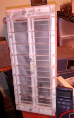
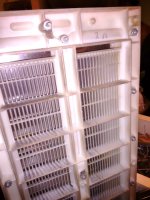
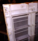
For 3D printing or if looking for a luminaire lens, here's the mechanical engineering of the DW cells for period 1970-80 roughly. The front and back moldings are identical.
The top snap-on lug is the diaphragm (one at other end too). In the middle are two lugs for the front and back stators. The stator conductors are silver paint and you can see some silver paint overspray that looks like a shadow. Embedded within the two stator holdings are some 20 Meg resistors.
I'm biased, but after seeing the MIL-Spec-like DW gear, other famous equipment looks like it was made in somebody's garage.
Ben
Attachments
Last edited:
For 3D printing or if looking for a luminaire lens, here's the mechanical engineering of the DW cells for period 1970-80 roughly. The front and back moldings are identical.
The top snap-on lug is the diaphragm (one at other end too). In the middle are two lugs for the front and back stators. The stator conductors are silver paint and you can see some silver paint overspray that looks like a shadow. Embedded within the two stator holdings are some 20 Meg resistors.
I'm biased, but after seeing the MIL-Spec-like DW gear, other famous equipment looks like it was made in somebody's garage.
Ben
Very interesting! The cells were made via injection molding and molds are still expensive today and certainly were more expensive in the 70th, probably too expensive for a small scale manufacturer which makes me think that originally the cells had a different application. I wander what could it be process chemical equipment, ventilation? Finding something similar and using conductive inks instead of wires or TIG rods certainly sounds more appealing. The network would have to be more dense. I believe DW cells were filled with sulfur hexafluoride and were driven at > 10kV.
Last edited:
Yeah, transformers seem to be the biggest road block to building high sensitivity ESLs that go lower than 200-300Hz.It’s a good question and I don’t have a definite answer. Depending on the diaphragm resonance which I can try to tune I can probably get a decent response down to 60Hz. However I don’t think I can run VTX-146-050-106 transformers below 100Hz.
As mentioned in another thread, the Acoustat transformers for the Spectra 11 would work great for DIY segmented ESLs. Step-up ratio is 142:1 and they can handle 30Vrms @ 100Hz. I happen to have a pair I plan to sell soon, or you can keep your eye on ebay. If you decide you really want to go lower than 100Hz, I still have a few 140:1 transformers built for segmented ESLs that can handle 40Vrms @ 60Hz…send me PM if/when interested in either.
Didn’t Dayton Wright only use the silver painted plastic stators for a few years?...here's the mechanical engineering of the DW cells for period 1970-80 roughly. The front and back moldings are identical... The stator conductors are silver paint and you can see some silver paint overspray that looks like a shadow.
From my reading of available literature it looks like most DW panels were built with un-insulated metal stators supported by injection molded plastic frames. Mike Wright definitely felt that un-insulated stators would provide the best dynamics without soft-limiting the peaks. Of course with un-insulated stator, you need to make sure that there is enough margin built into the design to avoid arcing and destroying the panels. This would usually result in lower sensitivity, but the SF6 gas certainly helped with that.
BTW, the original Quad ESL stators were also constructed using a conductive spray coating applied to plastic (perforated plates).
Guesses:Didn’t Dayton Wright only use the silver painted plastic stators for a few years?
From my reading of available literature it looks like most DW panels were built with un-insulated metal stators supported by injection molded plastic frames. Mike Wright definitely felt that un-insulated stators would provide the best dynamics without soft-limiting the peaks. Of course with un-insulated stator, you need to make sure that there is enough margin built into the design to avoid arcing and destroying the panels. This would usually result in lower sensitivity, but the SF6 gas certainly helped with that.
Wright made choices and changes based on factors not always patent to lesser beings like me, including mysterious economic issues sometimes related to dust-ups with suppliers and regulatory bodies. In other words, if he stopped using silver paint (likely uninsulated) as the conductor, hard to say why.
Later models had stamped steel pieces riveted on to the exterior, I think. For added rigidity? Of course, a great advantage of using sculpted molded stators is their strength arising from their depth.
The DW system entailed big spacing, high bias voltage, dry gas, and using rare stable 400 wpc amps driving 1:100 transformers.
Ben
Last edited:
Yeah, transformers seem to be the biggest road block to building high sensitivity ESLs that go lower than 200-300Hz.
As mentioned in another thread, the Acoustat transformers for the Spectra 11 would work great for DIY segmented ESLs. Step-up ratio is 142:1 and they can handle 30Vrms @ 100Hz. I happen to have a pair I plan to sell soon, or you can keep your eye on ebay. If you decide you really want to go lower than 100Hz, I still have a few 140:1 transformers built for segmented ESLs that can handle 40Vrms @ 60Hz…send me PM if/when interested in either.
I'm really tempted to try full range. Besides the resonance and dynamics my major concern is creating an amp killer. I will get in touch with you.
Full range ESL's are a different animal.... I initially wanted to do a full range but decided against it for my 1st build. They have more complexities, the transformer is just one of them.
Research long and hard before you dive into full rangers.... there is a reason commercial makers go with hybrids 🙂.
I'm aware of technical problems (difficult impedance) associated with the full range approach. However limiting panel range at 200 Hz-300Hz seems creates its own problems. Its difficult to maintain D/S = 1+-0.1 mm with wire stators (much easier with perforated stators). Another big issue is the integration with the cone divers. I wonder how are you planning to deal with the integration in your design?
I'm aware of technical problems (difficult impedance) associated with the full range approach.
Something more elegant about doing ESL full-range instead of the less-simple approaches.
But, the transformer input impedance will jump all over the placed if the range is broad. You end up with an Ohm or two in series to protect the amp against very low impedances which then compromises the high frequency output. Or you start configuring complicated input circuits kind of like the 18-element crossovers you see on expensive speakers today.
So I guess I'd head down the full-range transformer path but ready to carefully plot the input impedance curve.
Ben
Seems so simple just to find a pair of luminaire "egg crate" "lenses" and paint on the conductors.
Ben
Look on page 11 of the downloadable manual and you will see exactly what I am recommending being used in the fancy Sombetzki ESLs.
This reference was posted by Calvin on the Sombetzki thread, in this forum recently:
http://www.sombetzki-elektrostaten....93503/elektrostatischer_regielautsprecher.pdf
Ben
Your recommendation in post #7 was to paint conductors on to the louvers.Look on page 11 of the downloadable manual and you will see exactly what I am recommending...
The Sombetzki "PRO" panels you linked to appear to use the time tested Acoustat construction technique of insulated wires glued to louvers.
- Status
- Not open for further replies.
- Home
- Loudspeakers
- Planars & Exotics
- Louver based, PVC insulated Segmented Wire Stator ESL