Buy or Build Loudspeaker Protection Circuit
After you burn out some expensive speakers, you usually agree that loudspeaker protection is necessary. If you have built an amp without it, consider adding it.
The discussion at Rod Elliot's site is very helpful for understanding the problem and explaining his circuit solution. I suggest reviewing it. Though I consider his board a tad expensive with shipping cost added, I consider it fair to buy his products as compensation for his effort in clearly explaining the ideas and sharing them on the web.
Loudspeaker Protection and Muting
What functions are needed in the circuit? Let's assume we want to protect the speakers, not the amp. (Ideally the amp should have its own protection too, but that's very much dependent on the amp design and not my topic here. I just want to focus on the functions and designs for loudspeaker protection circuits, given a failing amp.) That means quickly disconnecting the output from the speakers. Practically speaking, relays are used for this, which have problems but are used almost universally.
Most designs disconnect the speaker from the amp using a relay. There are several triggers that should open the relay. Large DC offset is one. Loss of AC power is another. Overcurrent in the outputs is a third. Over temperature is a fourth. Finally, just for convenience you may want remote shutdown function and a turn on delay.
Very often an amp fails with output transistors shorted, which gives a large DC offset for a while until a fire starts or fuses blow. So sensing DC offset is a critical trigger. Sensing loss of AC is handy for preventing noise at turn on or turn off, and it's easy to add so we add it. A brief delay on turn on also is useful to avoid noises. Finally, there are miscellaneous functions that you can add as you prefer. Sensing overcurrent can be done in many ways, dependent on the amp's structure, so just having an input for it is the general solution. Overtemperature sensing again depends on the specific amp design, but to the protection circuit it's another input. A mute input is convenient. We should allow for all these options.
Any designer can come up with many circuits that do all these functions, using discrete devices or a ready made IC or other approaches. Rod Elliot suggests and sells one design, using discrete devices. You could use his design or build your own based on it. There are many similar ready made speaker protection boards sold on ebay which are similar.
These discrete circuits are simple and reliable, but not very adjustable or precise. They actually work well though. They work so well that people have made custom ICs that do pretty much the same functions the same way, but more compactly. Examples are the NEC UPC1237 and Toshiba TA7317. These are great building blocks and many commercial amplifiers use one or the other.
http://lib.chipdip.ru/035/DOC001035048.pdf
TA7317 Datasheet, PDF - Alldatasheet
You can build a protection circuit with these ICs using datasheets if you enjoy DIY, or buy a ready made one on ebay for a pittance.
30A Speaker Protection Board | eBay
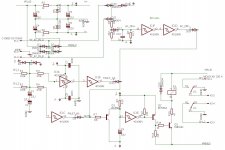
Another approach is to design your own, using opamps, comparators, 555 timers and other general purpose ICs. You can be more precise or choose different operating levels than the ready made circuits permit. So here are a few different approaches to show the range of possibilities.
Using an LM339 comparator, the Hafler DH 500 protection circuit works well.
http://www.hafler.com/pdf/archive/DH-500_amp_man.pdf
Below are three proto designs similar to the Hafler approach, using opamps, CMOS logic and discretes. These are just examples of DIY approaches that may suggest ideas for your own.
After you burn out some expensive speakers, you usually agree that loudspeaker protection is necessary. If you have built an amp without it, consider adding it.
The discussion at Rod Elliot's site is very helpful for understanding the problem and explaining his circuit solution. I suggest reviewing it. Though I consider his board a tad expensive with shipping cost added, I consider it fair to buy his products as compensation for his effort in clearly explaining the ideas and sharing them on the web.
Loudspeaker Protection and Muting
What functions are needed in the circuit? Let's assume we want to protect the speakers, not the amp. (Ideally the amp should have its own protection too, but that's very much dependent on the amp design and not my topic here. I just want to focus on the functions and designs for loudspeaker protection circuits, given a failing amp.) That means quickly disconnecting the output from the speakers. Practically speaking, relays are used for this, which have problems but are used almost universally.
Most designs disconnect the speaker from the amp using a relay. There are several triggers that should open the relay. Large DC offset is one. Loss of AC power is another. Overcurrent in the outputs is a third. Over temperature is a fourth. Finally, just for convenience you may want remote shutdown function and a turn on delay.
Very often an amp fails with output transistors shorted, which gives a large DC offset for a while until a fire starts or fuses blow. So sensing DC offset is a critical trigger. Sensing loss of AC is handy for preventing noise at turn on or turn off, and it's easy to add so we add it. A brief delay on turn on also is useful to avoid noises. Finally, there are miscellaneous functions that you can add as you prefer. Sensing overcurrent can be done in many ways, dependent on the amp's structure, so just having an input for it is the general solution. Overtemperature sensing again depends on the specific amp design, but to the protection circuit it's another input. A mute input is convenient. We should allow for all these options.
Any designer can come up with many circuits that do all these functions, using discrete devices or a ready made IC or other approaches. Rod Elliot suggests and sells one design, using discrete devices. You could use his design or build your own based on it. There are many similar ready made speaker protection boards sold on ebay which are similar.
These discrete circuits are simple and reliable, but not very adjustable or precise. They actually work well though. They work so well that people have made custom ICs that do pretty much the same functions the same way, but more compactly. Examples are the NEC UPC1237 and Toshiba TA7317. These are great building blocks and many commercial amplifiers use one or the other.
http://lib.chipdip.ru/035/DOC001035048.pdf
TA7317 Datasheet, PDF - Alldatasheet
You can build a protection circuit with these ICs using datasheets if you enjoy DIY, or buy a ready made one on ebay for a pittance.
30A Speaker Protection Board | eBay
Another approach is to design your own, using opamps, comparators, 555 timers and other general purpose ICs. You can be more precise or choose different operating levels than the ready made circuits permit. So here are a few different approaches to show the range of possibilities.
Using an LM339 comparator, the Hafler DH 500 protection circuit works well.
http://www.hafler.com/pdf/archive/DH-500_amp_man.pdf
Below are three proto designs similar to the Hafler approach, using opamps, CMOS logic and discretes. These are just examples of DIY approaches that may suggest ideas for your own.
Attachments


I have no luck finding upc1237, anyone know where to buy? One problem, it's not exact "u", it's really mu.
You can buy them here, dirt cheap.😀
https://www.utsource.net/ic-datasheet/UPC1237HA-366820.html
Per unit price is cheap. Shipping is very high, in the $15 range to US. Darn.
Vendors on ebay have the same part with cheap shipping too. A kit of parts with board is also very cheap there, even assembled is cheap. So cost is not a reason to skip loudspeaker protect circuit.
After you burn out some expensive speakers, you usually agree that loudspeaker protection is necessary. If you have built an amp without it, consider adding it.
Hi Slowhands,
You may be interested in our complex approach:
21-st century power amp control boards
The boards are versatile, flexible (microcontroller-based), robust (we use solid state relays and "reserved" protection circuits), protecting not only the speakers, but also the amplifier's output stage (especially with rails control option in place).
You can find a lot of details, schematics, etc. in "How to build a 21-st century protection board" thread here.
Cheers,
Valery
Attachments
Last edited:
EVERYDAY PRACTICAL ELECTRONICS december 2016 issue universal loud speaker protector
EPE Magazine December 2016
EPE Magazine December 2016
This schematic is too complicated for build (SMD transistors, too complicated topology of detecting overcurrent, and too many electronic components....), so most people at DIY prefer simple schematic and TH elements...and easy available.
When i have time, i will layout this universal speaker protection but with TH elements...because i don't like SMD parts.
And if you see closer above schematic from SC is basic idea of that is published in EPE (it is upgraded version of SC published a few years ago)
Anyway interesanting complex schematic.
All parts from utsource are fake!
I have buy some pic18f452 ,never successfully programmed.Oh really ?
All of them ?
I have buy some TL072 for using in a servo circuit,the result is a burned speaker!
Oh really ?
All of them ?
With all the reputable suppliers in North America, you could pretty much be sure if we can't buy it in this continent, it's likely not made any more. If it was possible to source, Mouser, Newark or Digikey would at least offer it as a special order.
With all the reputable suppliers in North America, you could pretty much be sure if we can't buy it in this continent, it's likely not made any more. If it was possible to source, Mouser, Newark or Digikey would at least offer it as a special order.
Wow. I never had an issue with them to that extend that they shipped outright fake components.
I have had once a single component that got perhaps mixed up with my order I guessed it was an honest mistake. Instead of 10 pcs. UPA68H they shipped 9 and 1 UPA66. It did not stand out until testing but was then obvious. For me no big deal really.
Parts (2SA995) I recently bought from them seem authentic unless they got really good with faking aging and oxidizing. The parts did test ok and work as expected.
But you guys sound like it be advisable to stay away from them. Do you have a recommendation besides Digikey and Mouser which seem to have dried up of the good stuff rather quickly.
As a test of UTsource, I have ordered 10off upc1237 and 10off 35A 1000V bridge rectifiers.
Cheap enough to bin if I don't like the look.
Any ideas on a testing regime to find out how close performance is to a genuine component?
Cheap enough to bin if I don't like the look.
Any ideas on a testing regime to find out how close performance is to a genuine component?
Wow. I never had an issue with them to that extend that they shipped outright fake components.
I have had once a single component that got perhaps mixed up with my order I guessed it was an honest mistake. Instead of 10 pcs. UPA68H they shipped 9 and 1 UPA66. It did not stand out until testing but was then obvious. For me no big deal really.
Parts (2SA995) I recently bought from them seem authentic unless they got really good with faking aging and oxidizing. The parts did test ok and work as expected.
But you guys sound like it be advisable to stay away from them. Do you have a recommendation besides Digikey and Mouser which seem to have dried up of the good stuff rather quickly.
I've never bought from them, so I can't personally say their parts are fake for sure. My theory is is the part is no longer in production from main stream suppliers, you don't need it. There are lots of alternative options available when building new. Repairing vintage equipment is a different situation and you may need to resort to questionable suppliers, but when building new, why take a chance?
As a test of UTsource, I have ordered 10off upc1237 and 10off 35A 1000V bridge rectifiers.
Cheap enough to bin if I don't like the look.
Any ideas on a testing regime to find out how close performance is to a genuine component?
The uPC1237 would be a simple test. Put it in breadboard and activate it's inputs and outputs repeatedly for a while. If it's self resetting (I'm not that familiar with the device) it's fairly easy to so with a signal generator. Set you generator to output a low frequency sine wave, and offset it so the output remains positive. it should repeatedly trip that way. Repeat the process with the offset to the negative side of zero. Follow this with square wave. Do this with a scope connected to the input and output and you can figure out trip points. On the datasheets I've seen, overcurrent should trigger around .6V, so a sine or square wave from a signal generator could do the same. I do this testing with all my DC detection and overcurrent protection systems.
If it's not self resetting, a test/reset routine with an Arduino would help you keep your sanity while doing repeated testing.
The diode testing would be a little more exciting, but I would do it outdoors at a bit of a distance. With one mounted on adequate heat sink, load it up to rated current and see it it explodes first. If you have access to a carbon pile high current testing is easy. If it survives that, repeat the load testing with AC and with an LED and resistor wired across the load oriented so it would light with reverse polarity current flow. If the LED lights you know the diodes leak. If you have a high voltage transformer and a known good diode, applying high voltage reverse polarity with your bulb limiter in series would let you know if they would withstand the voltage rating. If the bulb lights or blows, the diode failed.
I've never bought from them, so I can't personally say their parts are fake for sure. My theory is is the part is no longer in production from main stream suppliers, you don't need it. There are lots of alternative options available when building new. Repairing vintage equipment is a different situation and you may need to resort to questionable suppliers, but when building new, why take a chance?
I hear ya.
UPC1237
I have bought components from UTSource.
They seem to have stock of the UPC1237.
https://www.utsource.net/search.aspx?keyWords=upc1237&page=1
I have bought components from UTSource.
They seem to have stock of the UPC1237.
https://www.utsource.net/search.aspx?keyWords=upc1237&page=1
Help interpret Data sheet for uPC1237
Due to my specific use of the uPC1237 device, I'm checking scaling of components used for DC offset detection, applied to pin 2.
I have +70V -70V rails on Amp. 8 Ohm load. Mono Amp, NOT 2 channel.
Therefore, worst case scenario of 140V DC potential to speaker.
Yes?
So, thats the potential to consider in scaling devices in this section of the circuit?
The interpretation problem is with the original NEC data sheet that outlines component values and more so voltage rating of the associated capacitor noted as being 330uF.
The later edition UTC data sheet does not provide the above application information, however has an identical circuit diagram.
I regards to the Capacitor type [ polar or non-polar] and rate voltage.
I have seen a variety of circuits using a variety of components.
Data sheet shows 330uF polarised electrolytic.
All pre-made eBay offerings use 100uF / 50V polarised electrolytic.
Item shown in post #16 of this thread uses 2x series connected 680uF / ??V polarised electrolytic.
I have seen schematic on NAD Amp that also uses 2x series approach.
I have also seen suggestion that a NON-polarised component should be used.
In one circuit I have seen suggested voltage rating of Cap down to 6.3 Volts.
Unfortunately, nobody seems to want to mention the maximum input ratings of these manufactured boards, or more so the rail voltages of the Amp [worst case scenario they protect speakers from], they are suitable for.
Give they all seem to use relay switching, I'm going the MOSFET way, I'm assuming these boards are for less than 100W scale [if that] use.
So please, whats the correct reliable, long component life, flame free component to use here? Polarised electro or series connected polarised or non-polarised electro.
A non-polarised cap at 330uF / 160V. Are these even available or cheap?
In my application.... whats correct voltage rating of this Capacitor?
Also having trouble with Resistor value calculations going by the NEC application notes.
Perhaps a bit of 'lost in translation' makes it difficult to understand.
Can't understand the use of = value resistors [RA and RB ] application.
Is this applicable to my use on a mono input application?
The way I see it, pointless using for output DC protection if too low Ohm results in nuisance trip or over voltage to pin 2 or worse, never attaining threshold trip level applied to pin 2... and no protection afforded.
Big help needed... whats suitable values of RA and RC [or the RA and RB if applicable] as per NEC data, to use in my case?
I am also confused.
Ra, Rb & Rc are not labeled on the NEC diagrams.
I'm guessing that Rb & Rc are the speaker impedances and that Ra is the 56k shown attached to pin2.
Do you, or anyone, agree with this guess?
Edit,
no that guess can't be right, they end up with Rc = 94k
Ra, Rb & Rc are not labeled on the NEC diagrams.
I'm guessing that Rb & Rc are the speaker impedances and that Ra is the 56k shown attached to pin2.
Do you, or anyone, agree with this guess?
Edit,
no that guess can't be right, they end up with Rc = 94k
Last edited:
- Home
- Amplifiers
- Solid State
- Loudspeaker protection circuit