Hi,
Is it appropriate to expand this here or start a new thread?
Can a similar absolute level at the listener posistion be applied to dolby encoded recordings? or any other digital sources?
Does it imply that 105db is the maximum peak level that our systems should be listened to at ALL frequencies in the audio band? i.e THX are looking for 105db @20Hz from a compatible system and that we should not listen at levels exceeding this at any frequency.
All properly calibrated THX preamp/processors are setup such that 0dB on the volume knob causes 0dBFS to produce 105dB SPL at the listening position.
Is it appropriate to expand this here or start a new thread?
Can a similar absolute level at the listener posistion be applied to dolby encoded recordings? or any other digital sources?
Does it imply that 105db is the maximum peak level that our systems should be listened to at ALL frequencies in the audio band? i.e THX are looking for 105db @20Hz from a compatible system and that we should not listen at levels exceeding this at any frequency.
In post #10 in a thread in subwoofers, I introduce some core puzzles related to the equal loudness compensation that seem to be overlooked.
Hi FAB!I agree that the loudness setting has to be independently adjusted from the volume pot.
I also compensate for bad recordings where the bass has been forgotten...
This is the circuit I have come up with after several audio trials. It only increases the bass frequency gain. The main advantage of the circuit is that it is incorporated in the feedback path of your actual pre-amp so no need for additional active circuit. It can also be bypassed using a switch between connections 1 and 3 when not needed so no feedback cap in the audio path. The pot is shown as R3+R9 = 20K (linear). R10 is optional and the value can be adjusted if the pot value you have in hands does not provide the required compensation. U1 is shown to represent the active portion of the pre-amp since my real pre-amp circuit use discrete parts and not op-amps.
A very interesting circuit (schematics) of loudness! Is the frequency response curves have a diagram of the car?
When you connect the points 3 and 1 gets what, and when you combine 2 and 1 gets what?
Is in this circuit can be used IC=NE5532 or TL072 (stereo), and with whom symmetrical DC-voltage (+/-Ucc) is supplied to this circuit?
Thank you for your cooperation and cheers!

HiHi FAB!
A very interesting circuit (schematics) of loudness! Is the frequency response curves have a diagram of the car?
When you connect the points 3 and 1 gets what, and when you combine 2 and 1 gets what?
Is in this circuit can be used IC=NE5532 or TL072 (stereo), and with whom symmetrical DC-voltage (+/-Ucc) is supplied to this circuit?
Thank you for your cooperation and cheers!
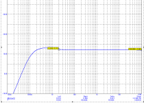
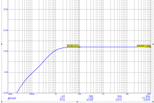
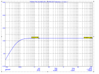
I have attached these graphs:
1) Max position of pot value
2) Min position of pot value
3) Bypass of the whole "Loudness" (bass only) circuit when not needed (between points 1 and 2)
4) Bypass of the "loudness" and the DC filter caps (when DC is not an issue)
Gain of pre-amp shown is about 12db.
It can be used with any opam such as NE5532, TL072, ...
The Loudness circuit is independent of the power supply voltage.
Thanks for your interest🙂
Good luck
Fab
Attachments

Active filter for 16kHz
Hello FAB!
How to construct a circuit with active filter for the rise of high frequency of 16kHz for around 5 ... 10 dB, also iaktivni filter to 50Hz for 10dB?
thank you!
Hello FAB!
How to construct a circuit with active filter for the rise of high frequency of 16kHz for around 5 ... 10 dB, also iaktivni filter to 50Hz for 10dB?
thank you!
Last edited:
- Status
- Not open for further replies.