Update
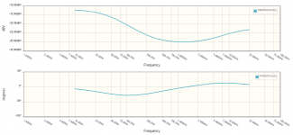
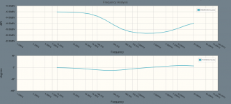
Finally, I obtained the results. I had drawn the circuit for the 30k-pot amp and divided pot into 15k + 15k. The resulted graph was reasonable. It was very close to the specs indicated. See attached.
However, when I moved to the 100k-pot amp and divided pot into 50k + 50k, the result was not close to the specs. Maybe there was an error from the pot reading. I'll try it again some times.
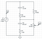
presscot, yes, that would be the equivalent circuit of center tapped potentiometer (for the volume range from zero to loudness tap).
Upper resistor (also part of the volume potentiometer) is not important for calculations of equalization. But it must be here, because of the LTSpice simuation.
So your circuit is good for LTSpice.
Finally, I obtained the results. I had drawn the circuit for the 30k-pot amp and divided pot into 15k + 15k. The resulted graph was reasonable. It was very close to the specs indicated. See attached.
However, when I moved to the 100k-pot amp and divided pot into 50k + 50k, the result was not close to the specs. Maybe there was an error from the pot reading. I'll try it again some times.
Attachments
Volume pot must be logarithmic, like in your post 13.
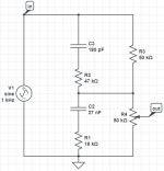
R3 = 10k, R4 = 90k (for simulation)
Probably, for simulation R4 must be log pot 90k.
Of course, in reality volume pot is R3 + R4 (100k)
R3 = 10k, R4 = 90k (for simulation)
Probably, for simulation R4 must be log pot 90k.
Of course, in reality volume pot is R3 + R4 (100k)
Don't know how it is in LTspice, but maybe it is easier to make simulation with discrete resistors like in my post 15.
But you must calculate those four (or any number) resistors in logarithmic proportions.
Than LTspice can simulate few different equalization curves, to show eq at different positions of volume knob.
But you must calculate those four (or any number) resistors in logarithmic proportions.
Than LTspice can simulate few different equalization curves, to show eq at different positions of volume knob.
My fault, the pot is indeed not 100k but 250k.
However, as I'd played with 250k, the resulted was still not reasonable.
First I started by dividing the pot into 125k + 125k, and the curve was not close to the specs as it was based at -25dB instead of -30dB as it should be. Then, I'd adjusted the upper part (R3/ fixed resistance) and lower part (R4/ pot) up and down alternately, still, I couldn't make it stayed at -30dB base. Does anybody have any ideas?
Last edited:
For -30dB point, R3/R4= 30
But then loudness tap will be on wrong position.
It's complicated, I will try to draw circuit a little later.
But then loudness tap will be on wrong position.
It's complicated, I will try to draw circuit a little later.

- Home
- Amplifiers
- Solid State
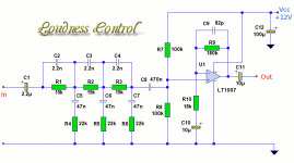
- Loudness circuit modification