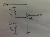
I'd like to modify the loudness circuit of my amp to work like another amp. After reading the schematics, fortunately, I found these two amps have the same loudness circuit! It is posted on attached.
The specs of my amp:
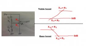
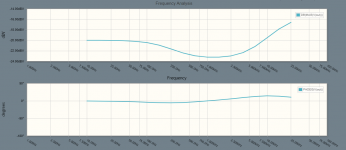
+8dB @ 100Hz
+6dB @ 10kHz
Component values:
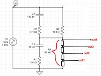
C1 = 180 pF
R1 = 47 kOhms
C2 = 0.027 uF
R2 = 18 kOhms
VR = 100 kOhms
The specs of the other amp:
+15dB @ 50Hz
+5dB @ 10kHz
Component values:
C1 = 1500 pF
R1 = 8.2 kOhms
C2 = 0.47 uF
R2 = 1 kOhms
VR = 30 kOhms
Can I change the values of the loudness circuit of my amp (C1, R1, C2, R2) to the same as those of the other amp?
The specs of my amp:
+8dB @ 100Hz
+6dB @ 10kHz
Component values:
C1 = 180 pF
R1 = 47 kOhms
C2 = 0.027 uF
R2 = 18 kOhms
VR = 100 kOhms
The specs of the other amp:
+15dB @ 50Hz
+5dB @ 10kHz
Component values:
C1 = 1500 pF
R1 = 8.2 kOhms
C2 = 0.47 uF
R2 = 1 kOhms
VR = 30 kOhms
Can I change the values of the loudness circuit of my amp (C1, R1, C2, R2) to the same as those of the other amp?
Attachments
Last edited:
Both specs are similar.
For calculation you need to know resistance of two parts of the volume potentiometer (before loudness tap, and after loudness tap).
Can I assume that it is 50% equal? Let say it is half of the full scale, 30k would be 15k and 15k, and 100k would be 50k and 50k.
I'd say "no", because of the different VR value. Unsure of your situation, as in do you have lots of spare parts hanging about / measurement stuff - or are you going to have to order the parts, so they need to be correctly calculated at the 1st shot.
Roughly, I'd try 540 pf and 0.1 in the 100K VR circuit - rather than going all the way to 1500 / .47; see if it moves in the direction you like. Should be easy enough if you have such bits kicking around.
Then order the parts in polystyrene or whatever cap formulation you prefer.
Roughly, I'd try 540 pf and 0.1 in the 100K VR circuit - rather than going all the way to 1500 / .47; see if it moves in the direction you like. Should be easy enough if you have such bits kicking around.
Then order the parts in polystyrene or whatever cap formulation you prefer.
Looks like a good opportunity to learn LTSPICE; it's free and can numerically solve this type of problem. It'll show the frequency response of the one you'd like to match and then the one you have. You can simply change component values iteratively until the curves meet up to what you want. Then order parts and rebuild.
It's a good area - electrical simulation - to have some experience in when this kind of problem comes up. There's some learning curve, but easy enough considering another issue like this one may arise in your audio pursuits!
It's a good area - electrical simulation - to have some experience in when this kind of problem comes up. There's some learning curve, but easy enough considering another issue like this one may arise in your audio pursuits!
Looks like a good opportunity to learn LTSPICE; it's free and can numerically solve this type of problem. It'll show the frequency response of the one you'd like to match and then the one you have. You can simply change component values iteratively until the curves meet up to what you want. Then order parts and rebuild.
It's a good area - electrical simulation - to have some experience in when this kind of problem comes up. There's some learning curve, but easy enough considering another issue like this one may arise in your audio pursuits!
Very well
") , I had tried on SPICE (online version) as your suggestion, preliminary, I got no results.
, I had tried on SPICE (online version) as your suggestion, preliminary, I got no results. Since the center tapped potentiometer symbol wasn't exist in SPICE. I wasn't sure whether I could draw the equivalent circuit correctly as seen on attached. Could anybody help to check for me, please?
Attachments
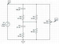
Circuit is not correct. Output must be from potentiometer, R4 must be divided to 10k + 80k and than output is in the joint of them.
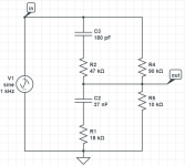
Do you mean the circuit should be like this? It looks like a Wheatstone bridge circuit. It had a weird result though.
Attachments
Circuit should be like this:
Out1, 2, 3 and 4 will show different eq curve, depending on position of wiper in volume pot.
Loudness will have most effect at Out1 position, (closer to the ground = lower volume) and will go to flat at Out4 position.
For that, you must divide R4 resistor (volume pot, part below loudness tap) into few resistors, to calculate it in LTspice.
Imagine that you have stepped attenuator volume potentiometer.
Attachments
Last edited:
Note the different volume control resistance of both amplifiers.
Unless you've got the opportunity to measure where the 30k's tap really is, I'd do the following: 30k volume controls presumably are hard to get. So check whether your existing amp would do fine with a 100k control. If so, get one, fit the passive components around it according your schematics and listen to your unit.
Best regards!
Circuit should be like this:
Out1, 2, 3 and 4 will show different eq curve, depending on position of wiper in volume pot.
Loudness will have most effect at Out1 position, (closer to the ground = lower volume) and will go to flat at Out4 position.
For that, you must divide R4 resistor (volume pot, part below loudness tap) into few resistors, to calculate it in LTspice.
Imagine that you have stepped attenuator volume potentiometer.
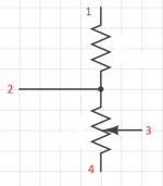
Do you mean that the equivalent circuit of center tapped potentiometer (4 terminals) should be like this?
Attachments
Note the different volume control resistance of both amplifiers.
Unless you've got the opportunity to measure where the 30k's tap really is, I'd do the following: 30k volume controls presumably are hard to get. So check whether your existing amp would do fine with a 100k control. If so, get one, fit the passive components around it according your schematics and listen to your unit.
Best regards!
I see the replacement or the upgrade unit for the amp with 30k pot on ebay is a blue ALPS 50k. So, it may be assumed that these amps will work fine with 50k pots.
presscot, yes, that would be the equivalent circuit of center tapped potentiometer (for the volume range from zero to loudness tap).
Upper resistor (also part of the volume potentiometer) is not important for calculations of equalization. But it must be here, because of the LTSpice simuation.
So your circuit is good for LTSpice.
Upper resistor (also part of the volume potentiometer) is not important for calculations of equalization. But it must be here, because of the LTSpice simuation.
So your circuit is good for LTSpice.
- Status
- This old topic is closed. If you want to reopen this topic, contact a moderator using the "Report Post" button.
- Home
- Amplifiers
- Solid State
- Loudness circuit modification