Normal vacuum tube filaments are designed to be driven by a voltage source. Their dynamic impedance is fairly high, that is, the current does not change much with varying voltage. Driving it by a current source gives unreliable heating power. Only filaments designed for series power (like in direct mains powered TV sets) will do proper driven from a current source.
Just my 2Ct 😉
Just my 2Ct 😉
Pjotr said:. . . . . .Driving it by a current source gives unreliable heating power. Only filaments designed for series power (like in direct mains powered TV sets) will do proper driven from a current source.
Just my 2Ct 😉
Hi Pete !
What you're saying is interesting , but it makes it curious that the verdict from those who have powered tube heaters and filaments from both Voltage and Current regs is almost unanimously in favour of Current regs. If you are correct (and I don't doubt you are) then I wonder if the two things are unrelated and current regs sound better for a different reason.
Hi,
For that your reasoning is probably right 😉 At low frequencies the filament supply should behave as a voltage source to ensure proper heating power. But the thermal time constant of the filament is pretty long, especially with indirect heated tubes. So the voltage source behaviour is not needed at higher frequencies and indeed an inductor in series will isolate the supply the higher the frequency goes.
I have no real experience how this will sound but my proposal is: Make a regulated supply and make the gain of the control loop dropping down with frequency. This will simulate a psu with inductive behaviour. You can make the frequency corner of the control loop quite low, but if you make is too low you get overshoot and instability at start up.
😉
Guys,
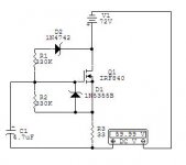
Is this a real gyrator then? I'm looking to drop about 10V from a 72V DC for use in a 150W amp. I considered the gyrator as a way to do this & get ripple reduction while I'm at it. I just put an additional 12 V zener (1N4742) in there to act as a regulator also.
Is this a real gyrator then? I'm looking to drop about 10V from a 72V DC for use in a 150W amp. I considered the gyrator as a way to do this & get ripple reduction while I'm at it. I just put an additional 12 V zener (1N4742) in there to act as a regulator also.
Attachments
Here's another example:
For the full text and explanation follow the link:
Capacitance Multiplier Power Supply Filter
An externally hosted image should be here but it was not working when we last tested it.
For the full text and explanation follow the link:
Capacitance Multiplier Power Supply Filter
- Status
- Not open for further replies.
