I saw something in the Baby Huey thread (great threads, and Kofi's is priceless!) and I'm hoping to get more info on it...
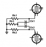
In the original version with cathode-biased EL84 outputs, there's a bit about using using two separate and bypassed cathode resistors (one Rk and Ck for each output tube) with the bottoms tied to a single 39 ohm resistor. This is supposed to reduce IM products and helps the clarity of the output.
I've attached a quick drawing of the circuit as I understand it from the Baby Huey thread (see below).
I understand Allen Wright's PP-1C EL34-triode amp uses this same trick (and used it a long time ago). That schematic is here:

I'm hoping this is applicable to all tube push-pull output stages that might wander into class AB. Questions:
1) How would one go about deciding on the proper value for the shared cathode resistor (Rk3 in my drawing)?
2) I noticed the Baby Huey uses 39R for Rk3 while the PP-1C has 68R. Does that mean the value is relatively uncritical?
3) Can something like this be accomplished with a single, common cathode resistor such as would be necessary with a pair of DHT's using a single filament transformer? Maybe a small value unbypassed resistor (say 47R) in series with the bypass capacitor, between the cap and ground? Or would that simply introduce a shelf in its low frequency response due to partial degeneration?
Thanks!
-=|=-
In the original version with cathode-biased EL84 outputs, there's a bit about using using two separate and bypassed cathode resistors (one Rk and Ck for each output tube) with the bottoms tied to a single 39 ohm resistor. This is supposed to reduce IM products and helps the clarity of the output.
I've attached a quick drawing of the circuit as I understand it from the Baby Huey thread (see below).
I understand Allen Wright's PP-1C EL34-triode amp uses this same trick (and used it a long time ago). That schematic is here:
I'm hoping this is applicable to all tube push-pull output stages that might wander into class AB. Questions:
1) How would one go about deciding on the proper value for the shared cathode resistor (Rk3 in my drawing)?
2) I noticed the Baby Huey uses 39R for Rk3 while the PP-1C has 68R. Does that mean the value is relatively uncritical?
3) Can something like this be accomplished with a single, common cathode resistor such as would be necessary with a pair of DHT's using a single filament transformer? Maybe a small value unbypassed resistor (say 47R) in series with the bypass capacitor, between the cap and ground? Or would that simply introduce a shelf in its low frequency response due to partial degeneration?
Thanks!
-=|=-
Attachments
Last edited by a moderator:
...And there's another, related, push-pull trick I'd like to ask about.
Lynn Olson, in a presentation made to the 2004 European Triode Festival, mentioned a Western Electric PP triode output circuit that's pretty standard except for a 10 to 40 uF capacitor from the B+ tap to the OPT center tap to the junction of the two cathodes in the output tubes pair.
Lynn was talking about the signal path in amplifiers and how they follow the current through the circuit (if I understand correctly, and it's likely that I don't!). I think the 10 to 40uF capacitor from B+ to the output tubes' cathodes bypasses the unbalanced current going through the tubes to ground to above ground, from cathode to plate to OPT winding to OPT CT back to cathodes, and so on.
Later on, Lynn mentions use of a CCS to force balance.
Hmmm... This is getting interesting.
Since I haven't seen these tricks put to use in any other amplifiers, I was wondering if there was any particular reason why -- especially the really easy trick of bypassing the OPT CT (B+ feed) to the joined cathodes of the output tubes. The reason I bring that one up is that I tried it with a 20uF 630V Solen cap and it seems to work really well. Nothing to measure with, unfortunately. I'm hoping to bring the amp to a friend's shop and see if any differences are observable on his 'scope.
Anyway, if anybody has experience with any of these strategies, I'd like to hear what you think of them. Always a learning experience...
Thanks.
Modified cathode circuit
The way the cathodes are connected somewhat resembles a differential amplifier that is commonly used in modern transistor amplifier input stages (transimpedance amplifier). That is it looks like the emmiter coupled circuit, only with cathodes. It should also provide a small amount of coupling out of phase/negative feedback, and balance, between the tubes. It is also in a way a pair of emitter resistors.
I am referring to the small schematic in the first post.
Last edited:
In the top circuit, there's degeneration to the extent that the cathode resistors aren't fully bypassed. My experience is that the difference between bypassed and not, results in a 6dB step in the frequency response. So a partial bypass as shown would adjust that shelf in the FR to somewhere between 0dB and 6dB.
In the Western Electric circuit, the CT of the output tranny is a Ground for AC due to the 100uF PS cap, so the 40uF or so cap would have exactly the same effect as if it when to DC ground, bypassing the cathode resistor.
Putting a current source in line with B+ , I don't see how that balances anything.
Here is the link for Lynn Olson's presentation: ETF Presentation
My interpretation is that he makes a distinction between "push pull" and "differential". Without the CCS, the tubes work in parallel - the definition of push pull - while a CCS will force the tubes to work in series - differential.
My interpretation is that he makes a distinction between "push pull" and "differential". Without the CCS, the tubes work in parallel - the definition of push pull - while a CCS will force the tubes to work in series - differential.
I saw something in the Baby Huey thread (great threads, and Kofi's is priceless!) and I'm hoping to get more info on it... <snip>
See Sheldons contribution to the BH Thread, Posts 451 and 452 EL84 Amp - Baby Huey
Cheers,
Ian
No, they work in push-pull in both cases - not parallel, not series. The CCS in the anode feed merely forces AC current balance but in a somewhat awkward way, because the anode is a poor place to influence a pentode. I suspect it is as likely to increase distortion as reduce it; it could reduce 2nd and raise 3rd.MagicBus said:My interpretation is that he makes a distinction between "push pull" and "differential". Without the CCS, the tubes work in parallel - the definition of push pull - while a CCS will force the tubes to work in series - differential.
The reason why you will not see these tricks used very often is that they are are tricks. Sometimes they work (with a particular valve, at a particular time) sometimes they don't. They sometimes swap one problem for another problem.
Indeed, I realize these are not universal tricks. I spotted that Lynn Olson avoided to speak about pentodes and class AB. Still not guaranteed to work with all triodes in classA. I just tried to focus on how the push pull power stage handles its own imbalance. It seems to me that the summation of the two antiphase signals is done in a different way in the "parallel" and "in series" models.
Last edited:
The impedance as seen by the two cathodes affects the overall harmonic spectrum, as well as peak current demand. A differential pair with a current source (as used by the late Allen Wright in his PP 300B amplifier) hits a hard current limit when one tube cuts off. (The current source sets a hard limit to the peak current delivery of the entire amplifier.)
It has to be kept in mind that the *peak* current of a vacuum tube can be 5 to 10 times higher than the quiescent current, and vacuum tubes don't normally need a current-limiting circuit as seen in transistor amplifier. True, if the tube gets too hot due to excessive dissipation on the plate, it can be damaged, but that takes a number of seconds before "red-plating" is seen. Transistor failure due to exceeding Safe Operating Area (SOA) happens in milliseconds, thus the need for active over-current protection circuits.
How often does a PP vacuum-tube amplifier leave Class A and go into Class AB, or even Class B? It depends on peak current demand from the loudspeakers, as well as reactive currents that are sent back to the amplifier. (Woofers are quite reactive around the low-frequency impedance peak.)
My auditioning of Allen Wright's PP 300B revealed the subjective difference between his current-source circuit and my amplifier (which has a conventional shared cathode resistor with a bypass cap) was audible at all signal levels, so the previous argument might not have too much weight. When we both listened to our respective PP 300B amplifiers, Allen preferred his amplifier, and I preferred mine, so I guess that's not conclusive of anything.
Last edited:
- Status
- Not open for further replies.
- Home
- Amplifiers
- Tubes / Valves
- Looking for simple Push-Pull tricks (from Baby Huey) #1