I don`t know if these tetrode tubes can be good for ESL drivers , but they are very high voltage radar modulator pulse tetrode tubes with Pd=60W, I have used them for AM transmitter , class C with B+ about 2,5KV , and those tubes works for years just OK , one was C1150 and second one was P552/1E , but Russian counterpart is GMI-83 , many simmilar types of radar pulse modulator tubes also exist .
http://www.r-type.org/exhib/abn0075.htm
http://www.r-type.org/exhib/aab0051.htm
https://www.gstube.com/photo/1405.jpg
http://www.r-type.org/exhib/abn0075.htm
http://www.r-type.org/exhib/aab0051.htm
https://www.gstube.com/photo/1405.jpg
Last edited:
PL519 (or other high current tube) is not likely to be well behaved down there. You’d probably have to run the screen down at 50 volts to do it, too. Bias will probably be all over the map between any two.How about 8mA at 4300V?
Jan
When those floating supplies have kilovolts between them it gets less and less practical. Small capacitances between things conduct enough AC current to cause trouble, or deliver a nasty shock to the user.Jan,
You can do what Crown calls a grounded bridge. You use two bridged amplifiers with separate floating power supplies. Then you can connect the bridged amplifiers in series.
I would run them in common grid with current drive into the cathode so bias is tightly controlled anyway.
Jan
Jan
Just over 20 years ago, I used PL519's in the thing described in the attachments. It worked well, but with only 2 kV peak, the output voltage was too small for the loudspeakers it had to drive. Most dangerous and most inefficient audio circuit I ever made... The screen grid voltage was indeed relatively low, and the biasing was very balanced thanks to the strong negative feedback around the valves.
Attachments

Hey Jan, I have an idea: What do you think of hi-voltage CRT or TV-screen-tubes where the beam is z-modulated?
Not going to get enough current with CRTs. And the phosphor coating will be high resistance.The special projection cathode can deliver 2 mA of beam current instead of the 0.3mA of normal CRT cathodes
What about a pushpull cascode if feedback is feasible to get the effective RP down to something acceptable?
I looked at some transmitting tetrodes like the 4CX1000, but the plate voltage rating at 3kV is not high enough.
Some interesting articles you might be aware of already:
http://sanderssoundsystems.com/comp...d-tube-amplifier-to-drive-electrostatics-1976
I looked at some transmitting tetrodes like the 4CX1000, but the plate voltage rating at 3kV is not high enough.
Some interesting articles you might be aware of already:
http://sanderssoundsystems.com/comp...d-tube-amplifier-to-drive-electrostatics-1976
Rp x load C could be frequency compensated somewhere upstream, but slewing (Ip x load C) limitations couldn't. How much C is a naked ESL63 anyway? Might be a complicated question with the delay lines and all. Could be calculated from its (unused here) input transformer ratio and external impedance curves? Anybody know?
All good fortune,
Chris
All good fortune,
Chris
Here's a transformer-reflected magnitude curve, not terrible at all:
https://www.stereophile.com/content/quad-esl-63-loudspeaker-measurements
but it would still be interesting to know a transformerless curve.
Jan has been happy with a (surprisingly?) small idling current, and that's an interesting data point. Just like Peter Walker to leave us with interesting questions.
All good fortune,
Chris
It shaping up in my mind. It looks like the best option is two // compactron or similar tubes, 6SJ6 like for instance. That gets me over 60W and peak voltages up to 8kV. Each at 10mA bias.
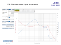
Attached is the impedance measured at the ESL 63 stators, and it's pretty benign, somewhere around 350-400k. Thanks to the transmission-line type of segmentation.
Jan
Attached is the impedance measured at the ESL 63 stators, and it's pretty benign, somewhere around 350-400k. Thanks to the transmission-line type of segmentation.
Jan
Attachments
Marcel, your design is well known to me! Inspiring.Just over 20 years ago, I used PL519's in the thing described in the attachments. It worked well, but with only 2 kV peak, the output voltage was too small for the loudspeakers it had to drive. Most dangerous and most inefficient audio circuit I ever made... The screen grid voltage was indeed relatively low, and the biasing was very balanced thanks to the strong negative feedback around the valves.
This whole new project strated from an insight I got from a suggestion by our friend Stuart Yaniger (SY).
I'm not ready to disclose it yet ...
My current direct drive amp, published in AudioXpress Dec 23 issue, outputs about 1.4kVrms which as you can expect, a bit anemic. The new design should double that.
Jan
Jan I know you know the Beveridge amps. They clip on the bench at 2,500Vp-p, so something a bit like these should get you to where you want to be.
As a data point the Bevamps are unkind to their tubes and run them at almost double their DCV rating. But it works.
Good luck with your project! Does the 63 lend itself to balanced drive or did you have to make some changes?
As a data point the Bevamps are unkind to their tubes and run them at almost double their DCV rating. But it works.
Good luck with your project! Does the 63 lend itself to balanced drive or did you have to make some changes?
2500 pk-pk is very low, like 850Vrms.
Mine do 1400Vrms and for the ESL63 that's not enough for full level.
The Beveridge probably has much smaller diaphragm-stator spacing for higher sensitivity.
I wonder how loud they go, SPL at 1W/1m anyone?
ESL is by definition balanced drive as they have two stators, front and back.
There have been some single ended designs in the past but they distort much more and are not successful.
Jan
Looking at that ESL impedance curve, it looks like 4 wavelengths of something. A ( transmission line ) termination resistor might have helped at really HF, but not for audio (line length too short). I suggest varying the membrane spacing slightly along that transmission line, so as to smear out the peaks and valleys into each other. Or, if there are 4 panel sections, changing their length or width some along the transmission line path to get peak/valley cancellation. Like 1.5/1 variation from start to finish maybe. If the peaks and valleys come from membrane tension/mass acoustic resonances, maybe make each panel section somewhat trapezoidal in shape. Could alternate the wide ends for every other panel section so they still fit together as a solid panel total. I'm sure there is some way to flatten that impedance curve.
Last edited:
A ( transmission line ) termination resistor might have helped at really HF, but not for audio.
See the upper right corner of https://www.meddens.eu/audio/esl63/quad63_schematic.gif
You suggest tearing into a perfectly fine ESL 63 - why?I suggest varying the membrane spacing slightly along that transmission line, so as to smear out the peaks and valleys into each other.
Jan
- Home
- Amplifiers
- Tubes / Valves
- Looking for high-voltage tubes