@ Galu Good point, my capacitance meter measured several 4.7uF capacitors in my components box at 4.7 to 4.9uF, a 22uF reads 23uF, and a 100uF at 102uF - so I trust the meter. I opened up my other Mission 70, and it's "4.7 MFD" BENNIC capacitor reads 22uF, way high like the first. I am going with the "running theory" that the electrolytic capacitors have dried out, plates closer, increased capacitance, more mid range frequencies getting to the tweeters, thus "mudding" them up. Not the regular failure mode of decreasing capacitance, though could explain why people "blow" tweeters in older speakers ?.
New Nichicon capacitors arrived, after measuring them, correct values seen, I replaced the BENNIC's. With a function generator and sound level meter did a crude before and after experiment. Running the tweeters only, I saw maybe a 10dB lowering of the sound level at 3kHz and 4kHz with the new capacitors. Agreeing with my theory that the old increased value BENNIC capacitors were letting to much mid range signal get to the tweeters. I can hear a noticeable improvement, increased clarity, which I could rationalize as the tweeters doing their job now without being "overdriven" by low frequencies - great. Think the tweeters themselves are OK and not "dry", they have had a gentle 40 years.
Thanks for finding and posting a picture of the inside of a Mission 70 MKII - looks like the same main driver and tweeter as my original. Differences are both units are recessed into the front wood, and as you say the X-over has atleast 1 extra component, also maybe the wood is thicker ?. The whathifi "Old speakers Vis New speakers" article of 2019 mentions with the Mission 70 MkII "Pretty much everything was changed", then "what was mediocre became budget class leader". The only thing I can really further do is upgrade the X-over per the "uprated crossover network", and if this achieves "sonic transformation" per the article, that would be great.
@ PeteMck Very interesting find - thanks, the first post in the chain mentions a MK II with only 2 components...... not the at least 3 of Galu's picture - so a mystery. I wrote to IAG (Chinees Mission owners) asking for a Mission 70 MK II X-over schematic - as of yet no reply. Maybe the Mission mid 80's MKII upgrade was not a clean manufacturing change from the original ?, but a series of production modifications, "covered" by a MK II label on the back to counter some bad initial reviews per the whathifi article.... sounds like something 1980's British ("land of the Morris Marina car") engineering would do !.
I went to my local Best Buy, and auditioned the B&W 606 S2 ($1000) - nice, but too metallic for my liking, not keen on the COA (Country of Origin) of China, though clearly showed the age and budget of my lower hi-fi Missions. I plan to raise a new thread asking if an owner of Mission 70 MKII's, with test equipment, could open them up and reverse engineer the X-over. Thanks for all the advice.
I am going with the "running theory" that the electrolytic capacitors have dried out, plates closer, increased capacitance...
The electrolytic spacer is actually the negative plate of a wet electrolytic capacitor, while the aluminium oxide film on the positive foil is the dielectric.
For an electrolytic capacitor that doesn't dry out, if the applied voltage is too low for a long time, the caustic electrolyte etches the oxide layer and capacitance increases - the negative and positive plates effectively coming closer together.
(Of course, a non-polar crossover electrolytic consists of two reverse series connected polarised electrolytics.)
the first post in the chain mentions a MK II with only 2 components...... not the at least 3 of Galu's picture
I have the 1985 Hi-Fi Choice magazine 'Special Issue' containing a report on the Mission 70 II in which the speaker rates a 'Best Buy' status.
The report states that the crossover uses "three electrical elements" and results in 12dB/octave acoustic slopes.
The mid/woofer obviously has its own natural HF roll-off which, when combined with the series inductor, results in the target slope.
The typical selling price was quoted as £109 per pair including VAT.
P.S. The19mm, polyamide dome Vifa tweeter is said to be "ferro-fluid damped".
Thanks Galu for your great comments, I poked about and found this :
https://electronics.stackexchange.c...c-capacitors-increase-in-capacitance-with-age
where the same increase in capacitance with age was noticed. Agreeing with you, an NCC apps engineer is quoted as "too low (a voltage) the insulation layer shrinks and capacitance grows." In my case, the 2 BENNIC 4.7MFD capacitors after 40 years of mild use becoming 22uF and 24uF, a factor of roughly 5 increase is quite something. Swapping in 2 new 4.7uF caps did noticeably improve the sound of my Mission 70's, less "muddy in the middle", and generally clearer.
If I understand right adding an inductor in series with the woofer/mid unit would have similar overall effect for me as the new capacitor. That is lowering the frequency response of the main unit so less "mid" sound, would really like to try it out. Did not hear back from IAG as to my request for a Mission 70 MKII schematic - so will post a new question. Hopefully someone with a Mission 70 MKII and equipment can reverse engineer the X-over. Thanks floridaclear

If I understand right adding an inductor in series with the woofer/mid unit would have similar overall effect for me as the new capacitor.
If an inductor were to be added in series with the woofer (which is presently running with no external filter), then the tweeter inductor and capacitor values would have to be different to match the new scenario.
You are correct, we need to find a Mission 70 II owner who is willing to measure the two inductors in its revised crossover, as well as telling us the value of the single capacitor. Going by the paucity of information on the interweb, that quest may not bear fruit.
If the sound with the new capacitors fitted now satisfies you, it may be time to sit back and simply enjoy the music!
Per Galu's great advice I have been sitting back and enjoying the music, finding the CD soundtrack of the Master and Commander movie a great speaker "tester". My setup is pretty "mid-fi", I still listen to cassette tapes through my Nakamichi BX-125, which sound "OK" with my original Mission 70's...... though do not have anything to A/B compare with. Still ponder the 2019 whathifi article describing with the Mission 70 MkII redesign "Pretty much everything was changed" then "sonic transformation".
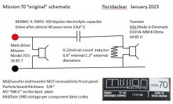
Detailing my Mission 70 original design in the attached schematic incase a MK II owner stumbles across this and has the equipment to describe their speakers. As far as I can ascertain "everything was changed" is circular routing the inside of the front wood panel to locate both drive units maybe 1/4" closer to the listener, a redesign of the X-over, and a new badge !. My thanks to all for their comments, floridaclear
Detailing my Mission 70 original design in the attached schematic incase a MK II owner stumbles across this and has the equipment to describe their speakers. As far as I can ascertain "everything was changed" is circular routing the inside of the front wood panel to locate both drive units maybe 1/4" closer to the listener, a redesign of the X-over, and a new badge !. My thanks to all for their comments, floridaclear
Attachments
The minimalist crossover arrangement shown was used to good effect in many loudspeakers, including the late 80s Mordaunt Short MS100 "High Definition" speakers I still make use of today.
The low pass filter is inherent in the design of the mid/woofer, producing a 6 dB/octave downward slope at the crossover frequency without the aid of an external inductor.
All good reason to be content with your Missions 70s!
The low pass filter is inherent in the design of the mid/woofer, producing a 6 dB/octave downward slope at the crossover frequency without the aid of an external inductor.
All good reason to be content with your Missions 70s!
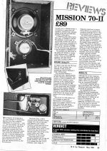
Update: brought down from my attic a 1980's Mission Cyrus 1 amplifier, my next restoration project. In the box was a 1984 review of the Mission 70-II, scan attached, I must have put in there 35+ years ago. The review has a photo of the X-over showing a 5.7uF cap instead of the 4.7uF marked units in my Mission 70's (that had both become low 20's uF over time !). Also an extra inductor in series with the main drive unit my 70 original does not have. If I understand right the designers were moving lower the frequency of the X-over between the tweeter and main unit. The Mission 70 appears to be somewhat of a "living design" during production - ah the good old days of the 1980's where the design crew had their office above or in the next building to the production line. In my view far better than todays "make stuff 1/2 way round the world at the cheapest subcon" business model. My speakers sound great (with a new bipolar cap) to my old ears. Costing just 80 GBP (< $100 at todays exchange) back in 1985 is testimony to the quality of vintage stuff, I was disappointed in a modern $1000 B&W speaker pair demo'd at Best Buy. Hope others find this interesting.
Attachments
Thanks, it's always nice to read those old reviews!
I would expect the Mark II to be more smooth and 'polite' than the Mark I, which is likely to give a livelier, more energetic presentation.
Some listeners may actually prefer the latter.
I would expect the Mark II to be more smooth and 'polite' than the Mark I, which is likely to give a livelier, more energetic presentation.
Some listeners may actually prefer the latter.
Probably a bit late but my Mission 70Mkii speakers were bought new by myself in 1984, after a shop then home audition (those were the days) - and I bought them along with a Creek 4049 amplifier and Dual (505 I think) turntable.
This was a good modest but capable system and it seemed to me that the Missions particularly suited their lounge, approximately 14ft square with slight irregularities such as the chimney breast.
Their lounge from that time is now mine, and although I have a "better" pair of speakers in the form of Linn Saras I am using the Missions. I haven't yet tried the Saras in this room but fear that their really deep bass response will overwhelm the room.
I haven't worked out the crossover yet on my pair but they have a further variation on those mentioned in this thread so far. They are a 5 element design which in due course I will try to get more detail on. But they have a 50V 5.7 micro farad capacitor (pretty sure it's an electrolytic) and, I think, a 50V 1.0 micro farad one. As I haven't worked out the circuit yet I'm assuming that the 5.7 is in the tweeter circuit with the 1.0 bypassing the bass/mid driver. There's one air cored inductor and one iron/ferrite cored inductor, additionally there is a resistor.
I'm attaching an uninspiring photo of the crossover.
BTW to me the main strengths of these speakers is their lack of nastiness to poor recordings and the way they respond well to being supplied by better front ends.
Attachments

Hi Alan!
Comparing your crossover to the crossover image shown in the attachment of post #49, the woofer is not simply rolled off gently by a series inductor (the iron core one), but more severely through the addition of a capacitor in parallel with the woofer.
The result is that both your tweeter and woofer are rolled off at 12 dB/octave instead of 6 dB/octave for just the woofer in post #49.
Your basic circuit is as below, with the addition of an attenuating resistor in series with the tweeter following the inductor.
P.S. Those capacitors are non polar electrolytics.
Last edited by a moderator:
Changing the dried out capacitors for some foil type will sure improve the sound. It did in their time and will be even more audible 40 years later. Do not spent much more than 10 pounds on these 4 parts, just good industry quality MKP, MKC or MKT. They need not be special "for audio" and even 63 Volt are OK, more does no harm. Leave the coils as they are, they do not degrade and their resistance is part of the tuning.
- Home
- Loudspeakers
- Multi-Way
- Looking for European vintage speaker advice