Some days ago, using the generous help of several friends in this forum, I could get to a power supply to be used on the low current stages of a power amplifier project I'm working. The thread was this:
https://www.diyaudio.com/forums/power-supplies/344416-using-lm317-voltages.html
I started the thread looking for help on a type of regulator, using 317/337 regulators, and was advised to follow a different path. Which I fortunately did.
Now I'm looking for a more sophisticated regulated power supply, as it will be used on some RIAA preamps I will be trying, and demands are a lot higher.
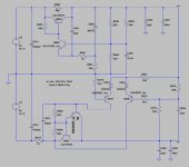
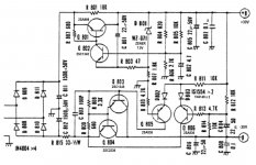
As one of the preamps I will be building is based on the Luxman 5C50 discrete preamp, let's start with the original manufacturer's PS for it.
Those shown are the original transistors, which do not exist anymore. So I started by looking for modern replacements and try to simulate it in LTSpice.
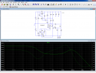
My LTS simulation only shows the output regulated voltage, but the curve is not right. Perhaps someone can correct what is wrong and fix it.
The idea is to simulate as much specs as possible.
Next in line are the Jung/Didden superregulator and LV's Dnoisator and NoNoiser. And perhaps some other one someone may suggest.
https://www.diyaudio.com/forums/power-supplies/344416-using-lm317-voltages.html
I started the thread looking for help on a type of regulator, using 317/337 regulators, and was advised to follow a different path. Which I fortunately did.
Now I'm looking for a more sophisticated regulated power supply, as it will be used on some RIAA preamps I will be trying, and demands are a lot higher.
As one of the preamps I will be building is based on the Luxman 5C50 discrete preamp, let's start with the original manufacturer's PS for it.
Those shown are the original transistors, which do not exist anymore. So I started by looking for modern replacements and try to simulate it in LTSpice.
My LTS simulation only shows the output regulated voltage, but the curve is not right. Perhaps someone can correct what is wrong and fix it.
The idea is to simulate as much specs as possible.
Next in line are the Jung/Didden superregulator and LV's Dnoisator and NoNoiser. And perhaps some other one someone may suggest.
Attachments
That is way too complicated for 2019. It also leaves out a couple of important features, like stripping RF from the power & signals coming in, surge protection, lightning pop reduction.
Start with one of these wall transformers, 36 v 1A: https://www.newark.com/xp-power/acm36us36/adaptor-medical-ac-dc-36v-1a/dp/43AC1942
although a 32 v adapter from a scrapped copy/fax/printer would be just as good. Produces more current than you probably need though, 3 A.
Run through a 1A fuse, then a choke like 11 turns on a toroid, then past a MOV surpressor rated for your country. Like on 125 v mains you want 175 v or so to minus. https://www.newark.com/littelfuse/v130la20bp/metal-oxide-varistor-175v-325v/dp/58K7218?st=metal%20oxide%20suppressor
You could alternately use a TVS diode, although I never have. The fuse has to be first because MOV surpressors fail shorted. I don't know about Brazil, but in the midwest US I've had ligtning hit a RIAA preamp so hard the power switch was tracked across "on" and the turn off pop capacitor, .01 uf @ 1000 v, was vaporized. You don't want that coming into your box. Two MOV supressors, one + to -, another - to safety ground, can prevent against lightning totally shorting out your wall transformer. Modem makers used to put in spark gaps, but MOV supressors are better IMHO.
Then a filter cap, about 2200 uf for amp. Smaller for 6 to 10 op amps. Parallel 0.1 uf 200 v. Then 7815 and 7915 regulators stacked. Then two 2200 uf caps stacked. for a pi filter to get hum even lower, you go to a resistor on the rails, say 2 ohm, then another couple of e-caps stacked. That is a pi filter. Parallel the filter caps with .1 uf ceramic disks.
That wall transformer keeps all the nasty hum out of your enclosure. Be sure to treat all inputs with 22 to 47 pf to signal ground coming in to eliminate RF. Use a steel box or aluminum line a plastic one. Safety ground the enclosure unless your turntable has a green wire, in that case make that the case ground.
If your RIAA circuit is single ended 24 v, use one 7824 and one filter capacitor per stage.
Happy building.
If you want ultra low hiss, then regulate a 2nd time to +-12 or something with one of those trendy LT ICs. I've got my disco mixer hiss & hum down below the sound of the pilot light on the heater with a choke, 5W zener diode stack, and a pi filter, but some people want the ultimate to brag about.
Last edited:
You need to make the source you test AC1:My LTS simulation only shows the output regulated voltage, but the curve is not right. Perhaps someone can correct what is wrong and fix it.
The circuit is basically a 2-transistor reg + a negative slave.
The startup method using R801 as a shunt is not very subtle or effective: it injects some of the raw input into the output and will degrade the DC/LF PSRR, and if the load is a bit difficult, it will fail to start
Attachments
If you can, always include the asc file.
So, the original supply definitely doesn't look as the way to go.
So let's go to the other options I mentioned, simulated under the same conditions.
So, the original supply definitely doesn't look as the way to go.
So let's go to the other options I mentioned, simulated under the same conditions.
I think you don't understand the way ACx works: ACx is the small signal stimulus, x being its amplitude.
Normally, we use AC1, because the graph is plotted wrt. that amplitude.
Sometimes, in transmission lines system for example, it is convenient to use AC2 to renormalize the graph after going through a line and its terminating impedances, but when there is no particular reason, 1 should be used.
In principle, we use one stimulus at a time, because injecting multiple stimuli here and there results in an incomprehensible mess.
Sometimes, multiple stimuli can be used: for example if V+ and V- have no circuit in common, making the two input sources AC1 allows the simultaneous testing of both channels in a single pass.
You might also want to examine the combined effect of synchronous input and output perturbations (not very realistic, but why not).
Otherwise, test one parameter at a time: input source for PSRR, output current for Zout, and switch off any other unused stimulus.
Your results will look more appealing
You are right that I do not understand how ACx works.
Can you please modify the asc file adding these changes? Perhaps then I can learn how to work with it.
If I'm going to compare regulators simulations, the variables have to be the same.
I already simulated the Dnoiser that's being analyzed on the Noizator thread, but it's quite certain the variables and other stuff are not right in order to make a comparison.
OK. 337 added and working.
What resistors do I trim to get to the output voltages I want?
I thought that splitting R8 and R16 in two resistors each, up and below Q2 and Q4 base, would give me that. But my try with my other sim didn't work.
Or is it that way and some other thing was wrong?
What resistors do I trim to get to the output voltages I want?
I thought that splitting R8 and R16 in two resistors each, up and below Q2 and Q4 base, would give me that. But my try with my other sim didn't work.
Or is it that way and some other thing was wrong?
Yes R8 and R16 should be adjustable potentiometers, but in the sim the three terminals are shorted to yield the nominal output (=midrange).
They are usable for fine-tuning only. The initial dimensioning should be based on R5 and R14.
Somewhere in the thread, I have given the formula's to compute the value: one is simplified, the other is unabridged.
They are usable for fine-tuning only. The initial dimensioning should be based on R5 and R14.
Somewhere in the thread, I have given the formula's to compute the value: one is simplified, the other is unabridged.
In order to understand this, you need to know the following:
The voltage between LM317 OUT and ADJ is ~1.25 V.
A BC557 E-B will drop another 0.65 V or so.
This gets us ~1.9 V down from the output.
Now this voltage will also appear across R3 + D1. (Assume R8 shorted.) If we approximate V(D1) ~= Veb(Q2) and Ib(Q2) negligible vs. Vout / (R3 + R5), then V(R3) ~= 1.25 V and
1.25 V / Vout = R3 / (R3 + R5)
Or in plain German,
Vout ~= 1.25 V * (1 + R5 / R3)
Which in turn you might recognize from the plain Jane LM317 circuit.
If you say you want to keep the current in this resistor divider constant, that means R3 = const, and Vout can be adjusted via R5, like Elvee says.
BTW, any estimates on how much current you'll need in the first place? This may be a bit oversized for just an RIAA.
Last edited:
OK. As the Luxman will need +/-30v regulated, I entered 40V into each input V and got +29.97 and -30.87. That would have to be trimmed on the actual regulator, apparently with R8 and R16.
Can't R8 and R16 be fixed values, instead of a trimpot? Then paralleling larger resistors with R5 and R14 would do the trimming.
Current needs for this preamp would be small: less than 13mA. If I'm looking for top quality, like on the superregulator, why would this be oversized?
Now: how do I do to measure output impedance and noise? Are there other things that have to be changed?
Attachments
I looked at this a few weeks back, I looked at over 20 commercial preamp's, read numerous threads here and on other forums, read various datasheet's and application notes, etc, etc. I tried regulated, both shunt and series pass, tried a capacitive multiplier, various R/L/C filters, valve based regulated PSU and several SS design's and a few others I've forgot.
In the end I got best results with lots of capacitance, in my case a pi filter using two 220u in series as the first cap (110u), then a 25H choke, with a 820u as the final cap, with two VR150's to clamp HT at 300v ish, ripple is around 100uV. I intend to decouple high gain stages with separate RC filters using 470u caps.
This may not be the best solution in your case, but it's simple, less to go wrong and for me with the mains tfmr I had and space limitations etc it was the right way to go. I wish I hadn't mucked about for two weeks, prevaricating and over thinking the problem, but I did learn a lot.
Andy.
I think power supply noise and low impedance are important in how the power supply affects audio quality.
If you don't need a continuous trimming and use paralleling for adjustment, you can delete completely R8 and R16, make R3 and R13 a more convenient E12 value, like 10K or 12K and adjust the voltage by paralleling R5/R14 with a high value, suitable resistor.Can't R8 and R16 be fixed values, instead of a trimpot? Then paralleling larger resistors with R5 and R14 would do the trimming.
It will be less noisy, and more stable in the long-term than a trimmer.
Note that unlike the regular LM317 circuit, this one is much less sensitive to trimmer imperfections, because it is used in potentiometer mode and the wiper current is very low, thanks to the buffer transistor
It is indeed oversized, but the 317 does not exist in L-version, and it is extremely cheap.Current needs for this preamp would be small: less than 13mA. If I'm looking for top quality, like on the superregulator, why would this be oversized?
With 13mA, you are going to load it enough to make it work properly, so why not?
It would be difficult to achieve similar performance with equivalent means, so it is a worthwhile proposition if you actually need the performance (and for a RIAA preamp, I think it can be justified)
Do you mean in sim or in the real world? The answer is going to be very differentNow: how do I do to measure output impedance and noise? Are there other things that have to be changed?
If you don't need a continuous trimming and use paralleling for adjustment, you can delete completely R8 and R16, make R3 and R13 a more convenient E12 value, like 10K or 12K and adjust the voltage by paralleling R5/R14 with a high value, suitable resistor.
It will be less noisy, and more stable in the long-term than a trimmer.
I guess the trimming has to be done with the actual parts. I wonder why I get slightly different values for the regulated output.
I imagine it's the different models I'm using for the regulators. Pity I couldn't find an LT1033 model, which would be the LT1085 complementary.
Do you mean in sim or in the real world? The answer is going to be very different
For the simulation, of course. So I can compare the different regulators.
I wouldn't have how to measure a superregulator, except for the output.
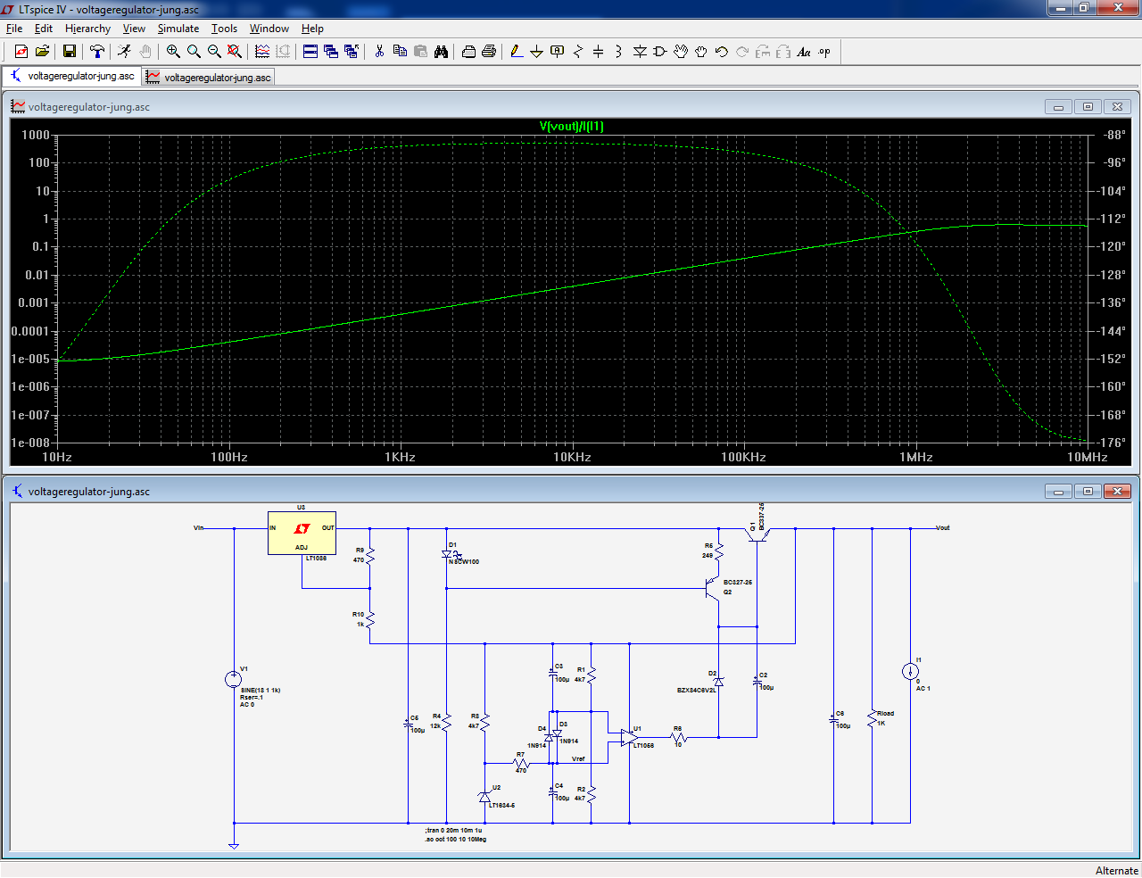
Uploaded is a superregulator simulation I found here in DIYAudio. There might be others.
In this case none of the important parts, opamp and main transistor are those recommended by Walt Jung or Jan Didden. The right models were not available.
Now I would like to learn to use LTSpice to run PSSR, noise and impedance, and also compare with other regulators.
In this case none of the important parts, opamp and main transistor are those recommended by Walt Jung or Jan Didden. The right models were not available.
Now I would like to learn to use LTSpice to run PSSR, noise and impedance, and also compare with other regulators.
Attachments
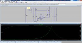
It's not correct because a)the regulator is broken, for some reason it does not work with the opamp you have selected, and b)you didn't turn off the AC1 input stimulus for the impedance measurement.
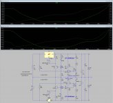
Using a more normal opamp like the LT1056 yields more realistic results:
Using a more normal opamp like the LT1056 yields more realistic results:
Attachments
It was not me who selected that opamp. I got the asc file here.
Voltage Regulators for Line Level Audio. Part VI : The Jung Super Regulator - diyAudio
And you are right: replacing the IC makes things right.
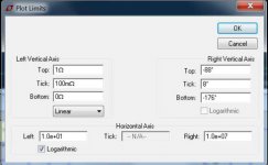
The impedance curve I'm getting is different from yours, but I think the problem is the Plot Limits data you are setting on the left.
Can you please show me what are the values I should load?
Voltage Regulators for Line Level Audio. Part VI : The Jung Super Regulator - diyAudio
And you are right: replacing the IC makes things right.
The impedance curve I'm getting is different from yours, but I think the problem is the Plot Limits data you are setting on the left.
Can you please show me what are the values I should load?
Attachments
- Home
- Amplifiers
- Power Supplies
- Looking for a good power supply for a RIAA preamp