Hello all,
I'm looking for a tried and tested amplifier I can build onto a small board. The supply voltage is 27V. It's needed to drive a 1.5" full range speaker, rated at 1W into 8 ohms. Signal feed is line level. NPN transistor design would be useful! Audio fidelity is not paramount but hopefully decent!
Thanks
You'll be better off with a few watts capability since the speaker rating won't account for signal peaks in its averaged maximum power rating. A 27VDC supply is plenty - too much actually - for even 10W so you may need a 3 terminal regulator for say, 12V (7812). Not knowing what end use and peak SPL you have in mind, I'd use a simple automotive chipamp like ol' faithful TDA2003. There are kits and boards in the US like this but its likely easier to follow the app. note and build on stripboard, if you wish but note the format of the copper grounding layout shown. That close-in, single point connection of grounds between input and output is important, however you go about it.
HTTP 301 This page has been moved
HTTP 301 This page has been moved
Last edited:
The maximum output of an amplifier fed with +27Vdc is just below half the supply voltage.
Expect the maximum output of a 27Vdc supply fed amplifier to be around 10Vpk to 12Vpk.
That equates to 6.25W to 9W into 8ohms dummy load.
IanF is absolutely right that you have chosen the wrong power supply if you want to meet your 1W target.
Choose a 15Vdc supply for a 2W amplifier, or a 12Vdc supply for a 1W amplifier.
These work and don't sound bad at all within their spec. I have tried them.
PAM8403 Mini Digital Power Amplifier Board Class D 2 3W 2 5 5V Input | eBay
//
PAM8403 Mini Digital Power Amplifier Board Class D 2 3W 2 5 5V Input | eBay
//
Is it really a Digital Power Amplifier?
or does the Retailer not have any clue about what they are selling?
To me (and I know almost nothing about the switching technologies) it looks like a bridged pair of switching amplifiers that need to be rated for a 2ohms load.
And how the heck does it manage 3W into 4ohms from a bridged pair?
A 1.5W into 2ohms amplifier is equivalent to 2.45Vpk and 1.22Apk
Two of them in bridged format will achieve the target of 3W into 4ohms.
Can that chip give 1.22Apk into a 2r0 resistive test load? Can it give 2.45Vpk into a 2r0 resistive test load when the supply is at the maximum of 5.5Vdc? That effectively means rail to rail output while delivering 1.22A !
Can it drive a reactive speaker load to these levels?
Is this yet another Retailer lying about their product?
Is it really a Digital Power Amplifier?
or does the Retailer not have any clue about what they are selling?
To me (and I know almost nothing about the switching technologies) it looks like a bridged pair of switching amplifiers that need to be rated for a 2ohms load.
And how the heck does it manage 3W into 4ohms from a bridged pair?
A 1.5W into 2ohms amplifier is equivalent to 2.45Vpk and 1.22Apk
Two of them in bridged format will achieve the target of 3W into 4ohms.
Can that chip give 1.22Apk into a 2r0 resistive test load? Can it give 2.45Vpk into a 2r0 resistive test load when the supply is at the maximum of 5.5Vdc? That effectively means rail to rail output while delivering 1.22A !
Can it drive a reactive speaker load to these levels?
Is this yet another Retailer lying about their product?
Well, have a look at this 😀
Mona
Attachments
Hi.
Agreed with all the above.
For my office/lab space I have built a TDA2004 amplifier. At 12 supply it is good for maybe 3 watts into 11 Ohm load.
Output p-p voltage sits at about 3/4 supply voltage maximum.
Driving some small 2" and 3" fullrange drivers it is easily clean and loud enough for my application.
Check the data sheet for the application circuit and PCB which I used. (It could do with an output inductor but I made a quick n dirty job since its only my office and cheap drivers)
Did you even look at the datasheet you linked?Well, have a look at this 😀
Mona
It clearly says Class-D
That is a switching amplifier topology.
It is not a digital power amplifier.
For the OP a decent 16/25 Ω speaker would do.
I mean, just raise the impedance of it and 27 V will work; I had lying around
a 25 Ω oval speaker from a radio diffusion set ( radio diffusion was BF trhru telephone cable 😕 )
I mean, just raise the impedance of it and 27 V will work; I had lying around
a 25 Ω oval speaker from a radio diffusion set ( radio diffusion was BF trhru telephone cable 😕 )
Lets not get carried away with unnecessary argument over distinctions between technologies. Yes, PAM8403 is class D rather than a mythical digital amplifier but does the precise term matter here with dinky chip amps? The device has a genuine datasheet, it makes noise and people use it because its small but mostly because it's dirt cheap. You get up to 1.4WPC at 1% THD into 8R with a 5V supply - atrocious distortion, presumably with both channels driven but it won't matter at probably lower average power levels.
'Pity about it needing a 5V supply when the OP has 27V supply though - rather inefficient unless you use a SMPS - another switching device that will be a lot more expensive and trouble to implement than the amp itself 🙄 I'd look around for a spare half-amp USB socket for that puppy.
'Pity about it needing a 5V supply when the OP has 27V supply though - rather inefficient unless you use a SMPS - another switching device that will be a lot more expensive and trouble to implement than the amp itself 🙄 I'd look around for a spare half-amp USB socket for that puppy.
http://www.ti.com/lit/ds/symlink/tpa6017a2.pdf
0.1% THD into 8 Ω, 5.5 volt supply, stereo, 1 watt at THD, each channel. $2.50 cost.
Dunno what else to say! Meets all OP's objectives including tiny, cheap, power, non-exotic quality. Can further drive dual-speakers without cross-over in parallel (4 OHM) at slightly higher THD, double output power.
GoatGuy
Well digital is on/off so is switching, for most people that's the same thing.Did you even look at the datasheet you linked?
It clearly says Class-D
That is a switching amplifier topology.
It is not a digital power amplifier.
So don't be so hard on those sellers.
Mona
But he has and wants to use a 27Vdc supply.
I hear they have these new fangled things called regulators. Which have certain features like regulation, radical ripple reduction, near-elimination of brute-force capacitors. 2.4 amp, 5.0 v, up to +35 V input, thru-hole. http://www.mouser.com/ds/2/405/lm340-n-405278.pdf
Just … saying.
I know it is way more fun to conceive of a quick little NPN amplifier (which so far has no input spec), but sometimes these practical little pieces of magic are all that one needs to solve real-world problems trivially.
The choices for a non-integrated solution are … huge.
• all NPN
• NPN & PNP
• Class A single ended
• Class A push-pull
• Class AB push-pull
• op-amp front end, discrete output
• super tech digital amplifier
• FET front end, LTP or even linear
• BJT linear front end (way-old school)
• either of the above with op-amp middle parts
• nuvistor front end…
Anyway, that whole list is just for fun, and would undoubtedly get hundreds of comments and counter-comments if asked as, “what is the best 2 watt per channel amplifier that can fit on a 50 by 50 mm board?”
GoatGuy
Thanks for all the replies. Maybe I should give some further detail, in case there are other alternatives you can suggest.
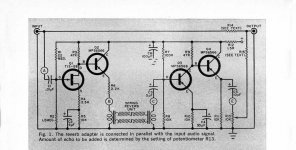
I want to experiment with a kind of mechanical feedback control for my spring reverb system (I'll attach the circuit I built). The purpose is to get some ringing/droning sounds while sound is played through the springs.
Originally I wanted to just use a pot to feed a controlled amount of the (100% reverberated) output signal back to the input, but after some experimenting I couldn't figure out how to make it work, not much helped by my lack of experience.
Enzo suggested in another thread that I could try aiming a small speaker at close range to the springs in the tank driven by an amplifier, fed from the reverb recovery output. The speaker I have is from the inside of a PC case.
The reason for the 27V supply is because the reverb drive/recovery amp requires ~30V to operate to its potential. The amp doesn't have to be 1W as such, so a higher powered amp will be OK if that's what my 27V supply dictates.
Attachments
I know it is way more fun to conceive of a quick little NPN amplifier
GoatGuy
You are certainly right, GoatGuy. I would definitely prefer that route, but if a little regulator and a 99c chip amp as posted above is the way to go, I will go that... way.
TDA7297 is really quite nice. Class AB and about as simple as it gets. Or do you require a discrete component design?
I can say that for purposes of a single full range drivers these are great. You need to drop your voltage though.
Online Shop 2*15W TDA7297 Dual-Channel 15W+15W Digital Amplifier Audio Amplifier AC/DC 12V 2A|Aliexpress Mobile
Add a DC-DC buck regulator:
AliExpress Mobile - Global Online Shopping for Apparel, Phones, Computers, Electronics, Fashion and more
But if you don't mind Class D, I can recommend this amp which sounds great below 10w and can take supply voltage as high as 32v. These are mono so you need two for stereo but superb sound quality. No turn on or off thump at all. Takes 27v natively.
http://m.aliexpress.com/item/32584429808.html
Last edited:
How about a LM386N-4.It accept power from voltages up to 18V. Put in a 7815 regulator IC to use 27V. Simple to do, https://www.youtube.com/watch?v=XHkKIEAo1vc
Mona
Mona
- Status
- Not open for further replies.
- Home
- Amplifiers
- Solid State
- looking for a compact ~1W 8ohm transistor amplifier design