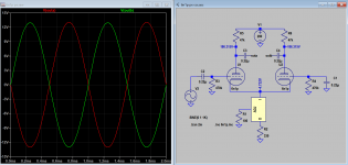
Sorry for the confusion, I guess I should have started a new thread. The schematic for this is at post#23. I posted on this thread because the suggested circuit at post #12 that I originally replied to was so similar. Maybe a moderator could break this out to a separate thread?Hello,
2M for grid resistors?
Try 470k
[
 Moderator Edit: post#23 above refers to post #1 in this thread. Post #12 above refers to the image here - https://www.diyaudio.com/community/...ailed-pair-phase-inverter.320241/post-5376399 ]
Last edited by a moderator:
Thank you for the suggestion. Ok, I added 1k to the 330r. Voltages now 284, 253, 237. Same issue. I used similar voltage range differences before for driver-cathodyne-power tubes without issue.As was said before the voltages 290V - 280V - 270V are too close , only 330ohm resistor is not enough between the output stage and phase inverter and then 1K for input stage is not enough either
Look at other schematics , something like 290V - 250V - 200V is normal
It's only when I connect the non-inverting section does the oscillation occur.
So both channels oscillate. You might want to disconnect the 1st tube (unplug) and inject signal into LTP and see what happens.
I have use LM317 with 6n1p, maybe it's the mismatch of impedance of the plate causing oscillation as plate resistor value is too far apart when 6n1p is used. Also the bias for LTP is only about 3V, with the gain of 14, the max. undistorted output is 52V. Try CCS approach if you can.
I have use LM317 with 6n1p, maybe it's the mismatch of impedance of the plate causing oscillation as plate resistor value is too far apart when 6n1p is used. Also the bias for LTP is only about 3V, with the gain of 14, the max. undistorted output is 52V. Try CCS approach if you can.
Attachments
Last edited:
I tried the LM317 CCS. Should have started out with that from the beginning. It works, and like you say, about 52V before clipping and oscillation. At the speaker terminals max output voltage is 16vpp, Only about 4.5 watts output for 12W6 in triode push-pull. I was hoping for more. Anyway, I know when I'm beat, and I'm beat.
I think I'm just going to convert this to a cathodyne phase splitter.
Thank you everyone for your help.
I think I'm just going to convert this to a cathodyne phase splitter.
Thank you everyone for your help.
At the speaker terminals max output voltage is 16vpp, Only about 4.5 watts output for 12W6 in triode push-pull. I was hoping for more. Anyway, I know when I'm beat, and I'm beat.
I think I'm just going to convert this to a cathodyne phase splitter.
Thank you everyone for your help.
But aside from the low power, aren't you experiencing the wonders of triode sound? Triode strapped drivers into triode strapped outputs, .... not WOWed by the magic? I mean, you even have LED biasing on the driver... gosh man...
Last edited:
I haven't even connected this to a music source yet. Just watching a boring 1kHz sine wave on an oscilloscope. I guess for a real treat I could change to 2kHz.
Seriously though yes, I like triode mode. I've already built a 12W6 parallel SE triode amp that sounds really nice, and I'm listening to a KT88 SE triode right now. Thank you for all of your suggestions 20to20.
Seriously though yes, I like triode mode. I've already built a 12W6 parallel SE triode amp that sounds really nice, and I'm listening to a KT88 SE triode right now. Thank you for all of your suggestions 20to20.
Thank you for all of your suggestions 20to20.
Glad you found the solution. But now I'm curious as to how you decided to try that 10M device for your driver loading?
Well, from reading diyaudio threads actually. Used as a CCS it presents an almost horizontal load line for maximum voltage swing. I've used it as the load for a 6N1P driver for my 12W6 PSE amp, and also for the 6J9P driver for my 2A3 direct coupled amp. Works great.
A constant current source tail to replace Rt will obviously improved the symmetricity of outputs.
Yes, RockyKing, thanks. I did change Rt to an LM317 CCS as suggested by Koonw in post #45 and it solved the issue I was having.
 Thread moved from here - https://www.diyaudio.com/community/threads/problem-with-long-tailed-pair-phase-inverter.320241/
- Home
- Amplifiers
- Tubes / Valves
- Long Tailed Pair phase inverter Oscillation
