If you think the design is wrong, you may want to try adjusting the value of the 51 ohm resistors along with the 10k resistor. Try replacing the 51 ohm with 100 ohm and then adjusting the pot to see if you can get clean audio with less DC offset.
If you draw a schematic diagram for one complete channel and go to the solid state forum, they can probably provide precise values for the entire amp.
If you draw a schematic diagram for one complete channel and go to the solid state forum, they can probably provide precise values for the entire amp.
Tonight I installed the 10K ohm trimmers and replaced the four 51 Ohm resistors with four 100 Ohm resistors. I have it dialed in for clean output, but now I have on each speaker terminal about -1VDC and unacceptable turn on/off thump.
Possibly went wrong direction going from 51 Ohms to 100 Ohms?
Possibly went wrong direction going from 51 Ohms to 100 Ohms?
Try one channel at a time.
If 100 was the wrong way to change them, try going to a 47. You won't be able to go really low.
It wouldn't take long to map out one channel. If you do that, the guys in the solid state forum could tell you all you need to know.
If 100 was the wrong way to change them, try going to a 47. You won't be able to go really low.
It wouldn't take long to map out one channel. If you do that, the guys in the solid state forum could tell you all you need to know.
After thinking about it, These aren't the resistors that need to be changed. Reinstall the 51 ohm resistors. There are two transistors with their emitters connected to the 51 ohm resistors. Either 1 or both of those transistors have their collectors connected to the positive rail (center leg of the NPN output transistors). What's the value of the those resistors?
Thats good because changing them up or down didn't have a good impact.
Yes, both do.
R107 (1K ohm) is between the collectors of Q106 (A1015) and Q109 (B778)
R108 (1K ohm) is between the collecotrs of Q107 (a1015) and Q109 (B778).
Yes, both do.
R107 (1K ohm) is between the collectors of Q106 (A1015) and Q109 (B778)
R108 (1K ohm) is between the collecotrs of Q107 (a1015) and Q109 (B778).
I think, before any more time is spent on trying to redesign the circuit, you need to replace all of the transistors in one channel. The parts are inexpensive (~$4/channel). I'm assuming that you've checked all of the resistors to confirm that all are within tolerance.
Mouser part numbers:
512-FJA4213OTU
512-FJA4313OTU
512-KSA1220AYS
512-KSC2690AYS
512-KSA1015YTA
512-KSC1815YTA
Mouser part numbers:
512-FJA4213OTU
512-FJA4313OTU
512-KSA1220AYS
512-KSC2690AYS
512-KSA1015YTA
512-KSC1815YTA
Perry, thank you for all of your help, past, present, and future.
Before I started this post, I checked all of the resistors in the circuit. The resistors that didn't measure what they were supposed to were removed and verified. So far every resistor has been within tolerance.
Should I return the original 10K Ohm resistors that I put trimmers in for?
I have KSA992 and KSC1845 on hand, can I sub those in place of the A1015 and C1815?
The ones you listed are rated for 1/3 the current so, without knowing more about the circuit, I'd say no.
If you have to order one of the parts, you may as well order all of them.
If you have to order one of the parts, you may as well order all of them.
I finally received and installed the new parts tonight. Unfortunately, there is no change to the symptom. I'll draw out one of the channels later on this weekend and post it for review.
I think I have the amp circuit layout mostly done using LTspiceIV. Now having done so, I didn't realize the file could not be up loaded here for viewing.
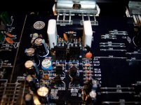
Would it be ok if I emailed the layout file and the photo of the whole component side of the board to you Perry?
Would it be ok if I emailed the layout file and the photo of the whole component side of the board to you Perry?
See if someone in the solid state forum will analyze the circuit. I could likely make it work if I had it here but it would take a bit of trial and error. With the LTSpice file, someone there should be able to analyze it and tell you precisely what you need to do to make it work.
Here is the LTSpice file, I think it is about 90% accurate, and a new picture showing the new parts installed for those following this thread. I have it posted in the solid state forum also. http://www.diyaudio.com/forums/solid-state/189911-distorted-ouputs-need-more-assistance-please.html
Attachments
Last edited:
I think I have this amp repaired. I touched up all of the solder joints and found some broken traces under a couple of electrolytics as well as a couple of components that just weren't making a connection even though they "looked" soldered. I installed new transistors in the other channel so that it matches the other. I still have the trimmers installed, but they are set at about 10K, so I could re-install the fixed resistors. There is practically 0.000VDC on the outputs.
I suspect this amp was probably mounted to a subwoofer box and it vibrated itself into this condition.
I suspect this amp was probably mounted to a subwoofer box and it vibrated itself into this condition.
I have a dx802 and Q209 and Q109 is 2SB778 and Q102 and Q202 is 2SD998 bit I need to know the part number for Q1 Q2 Q3 and Q4 and D! and D2 can any one help me
Last edited:
I no longer have this GX802 to look at.
In the GX802 I had, only Q2 & Q3 were populated with likely an IRFZ44 variant. I don't remember them exactly and I didn't document them as I wasn't having a power supply problem. If yours has 47 Ohm gate resistors, then an IRFZ44 variant might work in yours.
D1 & D2 were the rectifiers in the GX802. Sorry, I didn't document those part numbers.
- Status
- Not open for further replies.
- Home
- General Interest
- Car Audio
- Logic Soundlab GX802