No it doesn't at any point of raising the input signal or the gain levels or both either channel.
Here are some measurements taken with 1KHz tone set at 5.6mv on the RCA inputs and with the amp set at minimum gain with 4 Ohm speakers attached to the output terminals.
Channel 2 (Right)
Q109 - 2SB778 - Base =~30.0mVAC, Emitter =~15.9mVAC
Q102 - 2SD998 - Base =~29.3mVAC, Emitter =~15.9mVAC
Q108 - 2SB647 - Base =~31.6mVAC, Emitter =~31.3mVAC
Q101 - 2SD667 - Base =~30.4mVAC, Emitter =~30.4mVAC
Channel 1 (Left)
Q209 - 2SB778 - Base =~28.6mVAC, Emitter =~12.9mVAC
Q202 - 2SD998 - Base =~28.3mVAC, Emitter =~13.1mVAC
Q208 - 2SB647 - Base =~24.2mVAC, Emitter =~23.8mVAC
Q201 - 2SD667 - Base =~44.9mVAC, Emitter =~28.6mVAC
Last edited:
Post 2 more photos with exactly the same scope settings for both photos. Drive the amp until the bottom half of the waveform is clipped significantly. Post one photo of the base signal on the PNP output. Post another of the waveform on the emitter of the same transistor.
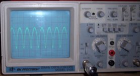
I'm assuming that the probe is a 10x probe and the scope was displaying 1v/div.
In the top half of the waveform, you can see that the base deflects about 1/2v more than the emitter. That's normal.
In the bottom half, you can see that the waveform extends well below the emitter (more than 1/2v) but the emitter doesn't follow. If the collector of the PNP transistor has constant rail voltage well beyond what's needed to produce this waveform, the transistor looks like it's defective.
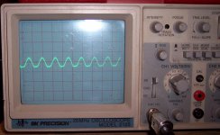
Probe is set at 1x not 10x so it is .1V/div.
In first post, wave form taken at output, the emitter eventually follows but at reduced voltage it looks like. I'll order up some new PNP outputs.
In first post, wave form taken at output, the emitter eventually follows but at reduced voltage it looks like. I'll order up some new PNP outputs.
Identical to PNP, both base and emitter.
I forgot to answer this earlier - the collectors are not rock steady but hover around 25.1v to 25.5V and -25.1V to -25.5V and are well beyond what is needed yes.
I forgot to answer this earlier - the collectors are not rock steady but hover around 25.1v to 25.5V and -25.1V to -25.5V and are well beyond what is needed yes.
I would expect the base to be much greater (off of the top of the display) on the NPN with a vertical amp setting of 0.1v/div. Are you sure they're identical?
Is that a 10k ohm resistor connected to the two 51 ohm resistors? If so, if you have another 10k-20k ohm resistor, touch it across the 10k resistor. Does that clean up the bottom half of the waveform?
Is that a 10k ohm resistor connected to the two 51 ohm resistors? If so, if you have another 10k-20k ohm resistor, touch it across the 10k resistor. Does that clean up the bottom half of the waveform?
I am sure they are identical. I am not driving much input signal at the RCA's, only 5.5mV.
There are two 10K ohm resistors R104 and R204.
I held another 10K ohm resistor accross R104 and tested Q109's emitter (the PNP), it cleaned up the bottom of the signal. I have not checked any thing further.
There are two 10K ohm resistors R104 and R204.
I held another 10K ohm resistor accross R104 and tested Q109's emitter (the PNP), it cleaned up the bottom of the signal. I have not checked any thing further.
I can't tell much without a schematic diagram or without knowing more about the circuit but the problem could be a lack of current through the differential amplifier. You may be able to reduce the value of that resistor so that there is sufficient drive for the rest of the amplifier. Most class B amps use dual differential amps. This one appears to have only one (per channel). This makes biasing (via the differential amp, like MTX and a few other use) more critical.
Using a 10k potentiometer, you could replace the resistor and adjust the pot just until the idle current increases. Then back it off until there is no DC voltage (0.000v) across the emitter resistors. Remove the pot and use a resistor of the value across the pot. Run it up to thermal to make sure the bias holds (very important). If the voltage across the emitter resistors doesn't hold at 0.000v DC at higher temperatures, the bias is too high and needs to be reduced.
Using a 10k potentiometer, you could replace the resistor and adjust the pot just until the idle current increases. Then back it off until there is no DC voltage (0.000v) across the emitter resistors. Remove the pot and use a resistor of the value across the pot. Run it up to thermal to make sure the bias holds (very important). If the voltage across the emitter resistors doesn't hold at 0.000v DC at higher temperatures, the bias is too high and needs to be reduced.
Well all I have thats fits the area of the board is a 100K pot. For testing purposes I installed it.
1. Adjustment of the resistance too low causes the wave form to be clean on bottom and distort on top, just the inverse of the original problem. This with the scope probe on the PNP emitter.
2. 100K pot is far too sensitive to leave in there or to even set it and then remove it to measure for the fixed value replacement. It might be better to solder it accross the original 10K resistor.
3. Now that the 10K resistor is out of circuit it measures within tolerance.
Last edited:
If the pot is an audio taper pot, try the center terminal and the other outside terminal. Audio pots have different tapers towards each end of rotation.
Radio Shack has pots.
Radio Shack has pots.
I dug around a little more and found two 23K trimmers.
Using two scope probes placed on the two PNP emitters I adjusted both trimmers to get good clean signal on both channels. The trimmer at R104 measures ~2.5K ohms and the trimmer at R204 measures ~15K ohms and sounds good playing music all through the range of gain and crossover adjustments.
The amp draws ~1.15A warm idle (no signal) but I haven't tested to thermal or measured voltage accross the emitter resistors nor did I test if it still sounded ok in bridged config. I'll have to do more testing tomorrow night.
In the meantime, Perry do you have any thoughts to why these settings are so far from the fixed 10K in each spot?
I don't know why they are so far off. It could be that the gain of one or more transistors is too low. They may have had a batch of weak transistors.
When you replace the pot with the resistor, you'll need to see if anything is getting hot. I'd be most concerned about the new resistors and the two transistors in each channel that have their emitters connected to the 51 ohm resistors.
When you replace the pot with the resistor, you'll need to see if anything is getting hot. I'd be most concerned about the new resistors and the two transistors in each channel that have their emitters connected to the 51 ohm resistors.
After more testing the trimmer settings listed previously were not good for bridged mode. Where I'm at now is I have placed a fixed 3.3K ohm resistor at R104 and I have a fixed 6.8K ohm resistor at R204. Nothing is getting hot, amp isn't drawing much idle current and seems to sound good in two channel mode. It's not perfect bridged and/or with the low pass crossover enabled. I am thinking a 7.5K or 8.2K ohm resistor at R204 may make an improvement.
Would an alternative fix be to return the 10K ohm resistors to R104 & R204 and replace the 2SA1015's?
Would an alternative fix be to return the 10K ohm resistors to R104 & R204 and replace the 2SA1015's?
With this type of fault, there may be no way to know (without experience with precisely this type of problem) the exact cause and replacing parts randomly in one channel may be the only way to find the fault. If you replace all of the transistors in one channel (just a few $ worth) and the problem still exists, changing the resistor value may be the only solution.
Is the voltage on one end of Q104/204 within a volt or so of the rail voltage?
Is the voltage on one end of Q104/204 within a volt or so of the rail voltage?
I was just about to button it up when I decided to measure the DC voltage on the output terminals. Channel one is up to .085VDC, influenced by R204 and channel 2 is up to .395 VDC influenced by R104. I may have to try to change out the 1015's.
I tried another pair of 1015's in channel two, and returned the 10K ohm resistor to R104. Same result as the original 1015's. So something wrong with the engineering?
I think I'll permanently install some Radio Shack 10K Ohm trimmers (271-282) in R104 and R204 to fine tune it better than the fixed values are giving, but I find the higher the DCV on the outputs, the more audible turn on/off thumps are, so......
I have read elsewhere what the maximum DC voltage on the outputs is desired but what is the maximum safe DC voltage and is there a way to minimize it once I have this biased to sound good?
- Status
- Not open for further replies.
- Home
- General Interest
- Car Audio
- Logic Soundlab GX802