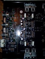
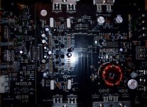
I have this amp opened up troubleshooting distorted output on both channels.
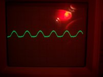
When I drive a 1KHz sine wave into to it unloaded the outputs look good. When I load it down with an 8 Ohm resistor the outputs look good also. When I drive full range speakers of ~5 Ohms it looks like the negative portion of the sine wave is the source of the distortion. The distortion is much worse when lower frequencies are used (like 20Hz) and worse yet when bridged (probably just because it is louder). The voltage level of input signal seems to also have an impact, the higher it is the better it seems to be.
I have checked the outputs (2SB778) and drivers (2SB647) out of circuit and they appear fine. I have checked most of the components (in circuit) around them nothing stands out.
Lightening the load by putting resistors in series with the speakers improves the sound quality.
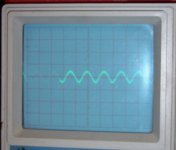
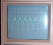
First picture is 500Hz tone, second is the same 500Hz with the amp's gain increased (source remained constant). These were taken with the scope probes accross the speaker terminals driving a 4 Ohm speaker (not bridged).
There is probably higher than normal DC on the speaker terminals at ~23.5mV, but its not adjustable and seemed resonable for an amplifier at this price point.
What am I missing?
When I drive a 1KHz sine wave into to it unloaded the outputs look good. When I load it down with an 8 Ohm resistor the outputs look good also. When I drive full range speakers of ~5 Ohms it looks like the negative portion of the sine wave is the source of the distortion. The distortion is much worse when lower frequencies are used (like 20Hz) and worse yet when bridged (probably just because it is louder). The voltage level of input signal seems to also have an impact, the higher it is the better it seems to be.
I have checked the outputs (2SB778) and drivers (2SB647) out of circuit and they appear fine. I have checked most of the components (in circuit) around them nothing stands out.
Lightening the load by putting resistors in series with the speakers improves the sound quality.
First picture is 500Hz tone, second is the same 500Hz with the amp's gain increased (source remained constant). These were taken with the scope probes accross the speaker terminals driving a 4 Ohm speaker (not bridged).
There is probably higher than normal DC on the speaker terminals at ~23.5mV, but its not adjustable and seemed resonable for an amplifier at this price point.
What am I missing?
Attachments

Check the emitter resistors to see if they're within tolerance.
If they're OK, confirm that the voltage on the emitter legs of the outputs remains the same for both channels when the channels are loaded with the same load (one channel at a time).
Can you consistently re-create this sequence of waveforms by changing the gain.
Do you get the same thing if you vary the input signal from the signal source (gain constant)?
Emitter resistors apear to be OK.
All emitter legs remain with in ~.5mVAC of each other when using a four Ohm speaker as the load.
Yes, I can consistantly re-create the waveforms by gain adjustment and by adjusting the signal source.
All emitter legs remain with in ~.5mVAC of each other when using a four Ohm speaker as the load.
Yes, I can consistantly re-create the waveforms by gain adjustment and by adjusting the signal source.
I think the PNP output transistor may be defective if this was taken on the base leg of the output transistor and the signal on the emitter was clipped.
Earlier I checked the 2SB778's and 2SB647's and they passed diode check. Tonight I checked the 2SD998's and 2SB667's and they passed diode check. My meter displays the diode symbol and the breakdown voltage as well as which test lead is on the anode and cathode. It also displays other symbols if it is damaged, leaking, open, or shorted.
Is it possible that they are defective and still pass diode check?
Is it possible that they are defective and still pass diode check?
It could be that the gain is very low and the meter isn't detecting it.
Swap it with the same part in another channel to see if the fault follows the transistor.
Swap it with the same part in another channel to see if the fault follows the transistor.
For the two 51 ohm resistors in each channel. Do they have one end of each directly connected? If so, what else does that end connect to?

Q103 = 2SC1815
Q104 = 2SC1815
Q105 = 2SC1815
Q106 = 2SA1015
Q107 = 2SA1015
Q101 = 2SD667
Q108 = 2SB647
Q102 = 2SD998
Q109 = 2SB778
Q104 = 2SC1815
Q105 = 2SC1815
Q106 = 2SA1015
Q107 = 2SA1015
Q101 = 2SD667
Q108 = 2SB647
Q102 = 2SD998
Q109 = 2SB778
I still think that the PNP outputs are defective (because their bases were being driven well below the emitters but the emitters weren't following) but if you want to draw out the rest of the circuit for one channel, I'll give you a few more things to check.
I was leaning toward the PNP driver. The driver has clean signal on it's base but both pictures shown earlier (post #5) taken from the Output's base/Driver's emitter, is less than perfect also. I will have to order either of them anyway, so I will order both drivers and outputs.
Last edited:
Is the base of the PNP output dropping more than ~1v below the emitter of the PNP output transistor?
- Status
- Not open for further replies.
- Home
- General Interest
- Car Audio
- Logic Soundlab GX802