not the alpha geek!
The output impedance decreases with increasing bias current for BJT and MOSFET followers (up to a certain point at very high bias currents) this is true for Sulzer regulators, three terminal regulators or simple followers since the regulated supplies open loop output impedance is generally determined by the output impedance of the pass transistor which is generally a follower. This is why preloading with a DC current higher than that required by the circuit under regulation is often a good idea. Some times brute force is a useful engineering approach.
"Intelligence and ability is all relative, and relatively speaking you are 1 smart guy, but amongst Alpha Centurions you might well be an idiot yourself."
Even among the really good engineers ( some who I highly suspect are from another planet) I have worked with I am the "idiot". I don't have problems with lack of knowledge just the lack of desire to learn from somebody with some real experience in a given area. The real "idiot" is the one who doesn't have a clue when he is in the presence of that person and can't tell the B.S. from advice of someone comfortable with a subject because he has done it. I have made that mistake but try not to make a habit of it. I have had my hat handed to me many plenty of times in technical matters. I really try not to go out on a limb discussing something that I don't have some experience and comfort with.
When learning to design and hearing something that I don't have the engineering knowledge to explain, it is time to go think and learn some more science and engineering related to possible explanations, not time to chuck the listening experience because understanding is not at hand. The engineering and listening experience tend to converge down the path and not to wildly diverge as so many here seem so convinced . I have spent so much effort in examining audio design I feel deserving of an honorary degree in the subject...... for about a week until I come across another topic that I am still somewhat ignorant in. It is real helpful to have a wife that is a classical musician, a wonderfull concert hall in Dallas, and the incredibly good fortune to talk to or write to some of the really great audio designers out there. Nelson Pass's influence started on me long before this forum through his excellent magazine articles. i learn a bit more with everyone of his post.
I am sorry for not showing a little more humility in the presence of real talent. With the level of experience of many of the people here, one falls into the mind set that "in the land of the blind the one eyed man is king." I think maybe most of my frustration stems from the shear effort and amount of time I have spent in the pursuit of this knowledge, rather than in any particular design accomplishment ( many very satisfing but always leaving one to wonder how much further you can go) This is very hard thing to explain to those who don't know the effort involved to get to this point. Literally hundreds of hours of listening to all kinds of highly regarded equipment and as much modifing it and designing my own.
The level of analysis skills demonstrated by andy_c and jbx puts me at about the level of being qualified to sharpen their pencils for their math analysis. My claim to fame in engineering is never to assume I knew enough to solve the problem off hand and to go find the book, ap note, data sheet, or guru to help dig me out of the technical corner into which I have been backed. Not really humility but much more akin to fear! One never wants to be the alpha geek in the group cause it is always comforting to have a smarter guy to pull you out off the hole in which you have fallen.
"When you have eliminated
the impossible, whatever remains, however improbable, must be the truth...”
An apparently under appreciated fundamental of op amp behavior is that their voltage gain is developed with reference to a power supply rail (most often the negative rail), it is easy to see that the ideal op amp model with the voltage gain stage screwed into ground is impossible when a physical op amp package doesn’t have a 0 Volt ground terminal. The commonly used Boyle macromodel enshrines this impossibility in the majority of spice op amp macromodels, the rarer “multiple-pole” spice models address this, see Analog Devices AN138 “SPICE Compatible Op Amp Macro-Models” http://www.analog.com/UploadedFiles/Application_Notes/1801016AN138.pdf
details the issues and gives a good modeling approach, unfortunately many of AD’s own op amp spice models do not employ this approach (the AD8610 model is a bastard “simplified” multiple pole model that has been hacked badly by someone ignorant of these issues), I use the TI/BB OPA227m (<= look for the “m”, accept no substitutes) model when I want some semblance rational floating/bootstrapped op amp model behavior
So in fact op amps do have near 0 dB power supply rejection with respect to the output when open loop, it is only the (excess loop) gain in a closed negative feedback loop that gives them any “PSRR” in a practical sense – ( most applications have large loop gain, the power supplies are ground referenced and don’t have too much voltage variation to reject anyway so probably >90% of op amp users will never look this deeply into PSRR)
From the thread:
PSRR, topologies, device characteristics
…for even more fun see:
“A General Relationship Between Amplifier Parameters, And Its Application to PSRR Improvement” E Sackinger, J Groette, W Guggenbuhl, IEEE Trans CAS vol 38, #10 10/83 pp 1171-1181
which gives:
1/(CMRR) + 1/(PSRR+) + 1/(PSRR-) = (1/Adiff) * Zload/(Zload+Zout)
as a fundamental relationship for the standard op amp, and shows ways around this limit by adding diff output or output ref to a amp circuit
( admit it, you’ve always wanted to say: “that’s an obvious consequence of the gauge-invariance of the electric potential field” )
Fred,
I am most impressed with your response; a balanced human being, where so many here appear to be single ended.........!
Now, my original questions:
1. Is there a correlation between good sonics and a vanishingly low Zout across the entire audible range (and beyond)?
2. If so, why does my zener reference emitter follower sound so damn good on a discrete opamp design I devised for my GK-1 preamp?
3. Is there any intrinsic quality of an emitter follower (and I am suspicious of it's falling Zout with rising current, and a strictly linear relationship) which makes it a good for sonics, and if not, as Elso has intimated, any ideas?
I can handle simple math. You know, Ohms law, the odd bracketed term, even a differential. BUT NO INTEGRATION PLEASE!!
Thank you, Alpha Centaurians, I appreciate it!
Cheers,
Hugh
the AD8610 model is a bastard “simplified” multiple pole model that has been hacked badly by someone ignorant of these issues
That's interesting, in some recent exchanges with the ADI app guys, I was told that the reason for the large backlog of SPICE models was due to ADI having lost a number of key SPICE modellers recently.
It may be worth highlighting such issues (which I'm lacking in ability to cogently argue) to make sure they are aware of the lack of model quality.
Andy.
Regulators,
I believe the TDA1543 is a special case. All my other solid state gear is powered by Jung regulators.
I don't know what is going on. I found this out by coincidence.
When I first powered up the TDA1543 in my DAC I connected it to the LT1086 used for the digital supply of my DAC. I was pleasently surprised by the nice sound. Then I thought why using the digital supply for the DACchip and I connected the TDA1543 to the Jung regulator of the analog supply. Result bad sound!
And now all the 47 Labs cloners are wondering what regulator is usd in 4715 Shigaraki DAC??? I guess a NJM7805 but I am not sure...
For my view about regulators see this thread on the Audio Asylum:
http://db.audioasylum.com/cgi/m.pl?forum=tweaks&n=36904&highlight=elso+regulator&r=&session=
😎
Hi Hugh,AKSA said:Elso, do you mean for every new circuit I devise I must revisit the power supply? Dammit!! I thought I'd saved myself some R&D!
Let me ask a question. Is it reasonable to suppose that a power supply with reducing Zout with increasing current draw, such as an emitter follower, would have different sonics to an active, opamp-based Sulzer with its vanishingly low but essentially constant Zout?
Cheers,
Hugh
I believe the TDA1543 is a special case. All my other solid state gear is powered by Jung regulators.
I don't know what is going on. I found this out by coincidence.
When I first powered up the TDA1543 in my DAC I connected it to the LT1086 used for the digital supply of my DAC. I was pleasently surprised by the nice sound. Then I thought why using the digital supply for the DACchip and I connected the TDA1543 to the Jung regulator of the analog supply. Result bad sound!
And now all the 47 Labs cloners are wondering what regulator is usd in 4715 Shigaraki DAC??? I guess a NJM7805 but I am not sure...
For my view about regulators see this thread on the Audio Asylum:
http://db.audioasylum.com/cgi/m.pl?forum=tweaks&n=36904&highlight=elso+regulator&r=&session=
😎
jcx said:[B[snip]So in fact op amps do have near 0 dB power supply rejection with respect to the output when open loop, it is only the (excess loop) gain in a closed negative feedback loop that gives them any “PSRR” in a practical sense – ( most applications have large loop gain, the power supplies are ground referenced and don’t have too much voltage variation to reject anyway so probably >90% of op amp users will never look this deeply into PSRR)[snip][/B]
jcx,
Being on holiday and sitting in a cybercafe with a quart of chablis under the belt doesn't really help to understand all those high-powered posts of the last three days. It did occur to me that referring the PSRR to the open-loop condition didn't seem right. But, following your reasoning, it seems that the PSRR necessarily should be the same as the open loop gain, then being reduced by the closed loop excess gain. If you are right, what is the point of separately specifying both olg and psrr - it would also mean all opamps are created equal - which we know not being the case - or do we?
Sorry to ask only questions instead of giving answers....
Jan Didden
did you feel any progress when you emptied the chablis...?
if not i could recommend a monrachet.........happy hollydays....
if not i could recommend a monrachet.........happy hollydays....
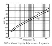
PSSR for poets
jbx-
"So in fact op amps do have near 0 dB power supply rejection"
dB at 100Hz AVL PSRR (positive supply)
OPA604 115 100
OPA627 105 120
AD8610 105 120
AD825 70 75
AD 797 120 130
*open loop gain rounded off to nearest 5 dB
It appears to be pretty small, 5 to 15 dB for these op amps at 100 Hz. These deltas are often not the same at other frequencies and both PSRR and AVL decrease with frequency.
Done under the influence of Cheerios and sugar. BTW Why can I never find any Gloomios at the store?
I despair
It started all very simple: I hoped building my stuff with op amps meant some halfways predictable behaviour assuming conservative circuits... Maybe that still works but any attempt at improving is a huge morass.
I had 78xx/79xx regulators with textbook/datasheet application, for preamp and active x-o (OPA 2134 based) and they worked fine. Then I tried LM317, shunt reg, even 78xx/79xx followed by power op amp as a regulator. It still works fine but no better and sometimes I suspect gremlins...
Assuming that a little noise is usually good (masking nastier artifacts / primitive 'dithering') I think I'll go back to the simple approach because I don't understand the fundamentals of the more sophisticated solutions.
Or maybe we need a "building with op amps" thread?
Amongst the things that I don't understand:
- if any standard op amp's closed loop PSRR at 120 Hz is around say, -100dB, why bother with a regulator? Doesn't the extra hassle to get rid of regulator problems far exceed the benefit?
- addendum: if an op amp is in reality referenced to the neg rail, wouldn't single supply operation (neg to gnd) fix a large part of the problem?
- special question: if high freq instability is the root cause of all problems, why not slow down the op amps bandwith to no more than say,100 kHz? Or use the slowest device on the market still able to handle 20 kHz audio?
- off topic but it bugs me: if as per OPA 2134 data sheet even a few nF capacitive loading lead to 50% small signal overshoot, how come any standard filter applications will unashamedly put dozens of nF (in series or to gnd) at the op amps' output?
I just don't get it...
MBK
but any attempt at improving is a huge morass.
You understand a lot more than you let on.
First of all an op amps PSRR fails with increasing frequency and is inversly propotional to the circuits gain. For a real opamp circuit you will see a lot less Power supply rejection than looking at those numbers would appear to indicate at first glance.
Bandwidth limiting an amplifiering above a 100KHz to 200KHz is areal good idea even for fast amplifier circuits used for audio application.
Op amps in active filters should not drive several nFs to ground. Maybe there is a resistor involved in this filter as well?
Keep asking good questions like this! They are dead on and useful to many others who wonder the same things.
Attachments
Originally posted by jcx
…for even more fun see:
“A General Relationship Between Amplifier Parameters, And Its Application to PSRR Improvement” E Sackinger, J Groette, W Guggenbuhl, IEEE Trans CAS vol 38, #10 10/83 pp 1171-1181
That sounds like a classic article. I will definitely try to get a hold of it one way or another. A colleague of mine tried to get it on the web for me but apparently he's only got an account that lets him access IEEE MTT. Maybe I can go to a library and make a copy.
I must say, this has been an incredibly thought-provoking thread. I never thought much about PSRR in an analytical sense before. It was always just "use a regulator and some bypassing and don't worry about the rest". But thinking about the design of the regulator itself really exposed my lack of knowledge here. Having been away from analog design for 10 years doing software for a living doesn't help much either.
Originally posted by Fred Dieckmann
Done under the influence of Cheerios and sugar. BTW Why can I never find any Gloomios at the store?
I was howling when I read this earlier today at work. People were looking in my office, wondering what was going on. Fortunately, I closed my browser in time 😉.
Gloomios
A highly developed sense of humor is a sure sign of intellect. I thought only Jocko might find this amusing. He knows me well enough to know I would eat Gloomios if they made it.
A highly developed sense of humor is a sure sign of intellect. I thought only Jocko might find this amusing. He knows me well enough to know I would eat Gloomios if they made it.
thanx for the data Fred, …always ready with fuel where there’s a fire
Jan,
PSRR curves do give some additional information not captured by the open loop gain curve:
1/(CMRR) + 1/(PSRR+) + 1/(PSRR-) = (1/Adiff) * Zload/(Zload+Zout)
The Sakinger paper’s result relates the sum of the common mode and psrr terms, this certainly allows for the possibility of differing behavior of several of the terms, commonly the psrr on the power supply rail that the Miller compensation cap is referenced to will closely follow the open loop gain curve and the other rail will have much better psrr. For the special case of the proposed def by AD of a single psrr # for balanced, opposing +/- psd, the “balanced psrr” can be high if the underlying psrr+, and psrr- numbers are nearly equal and opposite in sign (implying C_comp is split evenly between the rails) – unfortunately load induced psd is not likely to be balanced with class B output amplifiers.
Consider an open loop op amp with the diff input voltage set to hold the output exactly centered between the supply rails, no current is flowing into the compensation and device capacitances (remember I = C*dV/dT, V constant => dV/dT = 0), now move both supplies up 1 V, and you can see that you have 0 dB supply rejection since the op amp output has to move the same 1 V if the charge on the internal C didn’t change (if the differential input voltage doesn’t change we get no I out of the input gm, assuming no common mode input offset effect – Sakinger’s relation even allows for op amp Zout)
Bob Pease covers op amp CMRR measurement errors in his book, considering these types of measurement error combined with some uncertainty in each manufacturer’s definitions and measurement practice I feel Fred’s data sheet numbers offer more support to Sakinger’s relation than countering it.
I have used the theory in modeling multiloop amplifiers and verified the predictions against real world circuit measurements (at least over 20KHz – 1 MHz where I could find the signal in the noise while not over-driving the circuit)
Fred,
I guess I know enough to be aware of many issues, but I'm not surefooted enough to hande them in a "clean engineering" sort of way. I don't even get to try all these popular tweaks anymore ;-) ... because I have such a hard time to handle the basic engineering: GBW, input series R, R(+ in) vs. R (- in), PSRR, capacitive loading, headroom in I and V, stability, grounding...
PSRR: my point was, since op amp PSRR is best at low f, it should be good enough to take care of the low f ripple of an unregulated supply in low gain applications, such as my preamp (gain hardly over 12 dB) and x-o (unity gain). Conversely the lower PSRR at high f will have a hard time to reject the potential high f artifacts created by ... a regulator.
My chip power amps for instance (OPA548) with unregulated supply and 26 dB gain don't have the slightest buzz. Some very minor noise is audible but only at no more than 1-2 " from the speaker (89 dB eff).
Capacitive loading: How about a capacitor in series with an op amp output? I always try to "picture" what actually happens to the electrons 🙂 : I figure in the first nanoseconds of an AC pulse the capacitor is essentially seen by the amp as an empty charge plate to be filled with electrons. This means basically a short circuit, damped only by the real Zout and the ESR of the cap. Won't the op amp have a real problem especially with current capability during an initial, short time period?
This thought occurred to me during a breadboard session where i built a simple AC coupling filter, 2.2 uF series and 20k to gnd, driven from preamp. It wrecked perceived dynamics completely, and sounded "edgy". I had a couple of different types and brands of 2.2 u caps lying around, tried them all. Type of cap didn't matter. Only by changing the value to a smaller cap (and therefore higher f(-3 dB) which should make things worse) did things get close to the response of the straight wire (there was no DC on that circuit so I could just take it out altogether for comparison).
MBK
capacitive load reference
I found the reference that made me think of capacitive loading in seemingly innocuous textbook filters:
http://www.jensen-transformers.com/an/an001.pdf
(on page 4)
MBK
I found the reference that made me think of capacitive loading in seemingly innocuous textbook filters:
http://www.jensen-transformers.com/an/an001.pdf
(on page 4)
MBK
Lies, data sheets, and statistics
I come not to add fuel to fire but just to introduce some very limited data to look at the relationships between PSRR+ and AVL. One really should look at the data sheets to see the relationship between PSRR+,PSRR, CMRR, and AVL and the change as function of frequency. The point on measurement difficulty at audio frequencies is well taken and 120 dB represents the ratio between 1 volt and 1 microvolt. Measurements in even the tens of microvolts are quite interesting to make.
It worth reflecting that looking at these high PSRR numbers gives one a tendency to be complacent about supply regulation. The subjective tweakers on the other hand, are usually amazed at the role power supplies play in the sound of circuits. The point of sonic diminishing returns for design improvements, seems to be at a point far beyond what one would consider as design overkill in regulator design. Very good power supply design does play a very large factor in good sonics even in circuits with op amps having much better PSRR numbers than some of our discreet designs.
It is worth noting that Walt Jung, a highly skilled applications engineer and op amp expert, is the one most vigorously pursuing the effect of power supplies on preamp sonics. The combination of acceptance of the fact that circuits sound different, and the exploration of the measurements that correlate with this differences, have always made for interesting reading. I believe accepting that circuits sound different. beyond our ability to measure them was expressed first by Mr. Jung in an article about modifying the Dynaco PAT 5 preamp published in the Audio Amateur in 1979. He has spent about a quarter of a century attempting to close that gap with some fascinating insights along the way. I applaud his stance which frequently found him in the crossfire between the subjective and objective schools of audio design.
Attachments
Fred,
I couldn't have written that better myself.
I've yet to find the point at which PSU imrpovements do not make significant differences. They affect every single piece of electronics we use for audio.
The discusssion above on PSRR etc. is extremely useful and may well prove educational but I'm not certain it will result in any clearly defined 'rules for power supplies'.
Also do not overlook digital, much of our music comes via this route today and it's easy to become complacent about digital when the levels of precision required are ignored, through assumption or ignorance.
Jitter at the DAC in a CD replay system is audible to single digit picosecond values - anyone know the relationship between jitter / phase noise and the PSU noise on a 74HCU04 that the manufacturers are so keen on using?
I'm unusual amongst many DIY Audio types in that I've actually built very few circuits purely for topological reasons, as I've yet to find the limitations of many of the existing circuits I use.
I'd hoped a long time ago to have been able to draw a line under power supplies, having been-there, done-that. The magnitudes of improvement I continue to get though keep driving me on. Not subtleties, but the things even your Gran would hear (assuming she can still hear!).
Since the benefit if this research can then be applied to every single item I use, often easily, I get big bang, for sensible bucks (actually the bucks are escalating, but what the hell, can't take it with me).
One often get's rewards in unusual places; that rare ability to unequivocably correlate sonics with measurement can be a real joy - the real engineer can then be let loose and actually design for a goal. Sometimes the fix buggers up something else, leading one down another untrodden path of discovery.
Often though, the goals aren't really known - I'm not even sure whether I'm on the right pitch sometimes 😉
You absolutely MUST use your ears though - what measures better doesn't always sound better. Imay be measuring the wrong things, but that's a fruitless argument unless you can then tell me what to measure.
Your test equipment will tell you virtually nothing about how a circuit sounds, but it's a useful, sometimes essential tool in at least making sure the fundamentals are right, which are usually a pre-requisite.
This is the frustrating and also fun bit of audio. I don't think I'll ever tire of it, there's just so much to learn.
Agreed. Everytime you think you have conquered a problem area, you realise that you have just scratched the surface.
Jocko
Jocko
Will the circle be unbroken
"You absolutely MUST use your ears though -- what measures better doesn't always sound better. I may be measuring the wrong things, but that's a fruitless argument unless you can then tell me what to measure."
The next step after the "this sounds better" phase, is to measure and analyze the circuit from the standpoint of the topology, data sheet parameters, and even spice models. The correlation and even lack of correlation (i.e. measures better but sounds worse) will lead you down unexpected and often enlightening paths. The next stage of design often is focused on which measured parameters in the last permutation, were different from those in the less good previous version. The parameters can then be the focus for optimization for the next design iteration. These are not just measured parameters but can include things based on data sheets, Spice simulations, and even conceptual models (those things engineers draw on the white boards in their cubical.) PSRR rejection as a function of frequency would be a good example. Design steps to improve the circuit's input filtering for frequencies where the PSRR drops off might be examined. This circuit charge is then examined to see if these improvements degrade the performance at the frequencies where the PSRR was good. This process leads to the balancing act, optimizing one parameter without degrading the other too severely in the process. In production design you will have the constraints of cost, performance, reliability, complexity, manufacturability, obsolescence, backward compatibility, and opposition from management as to the relative importance of each, to consider. More likely the directive to have all of these features and have the design completed by the end of next week. Hobbyist have luxury of only having to focus on a few of these constraints. Every time I see the phrase "no compromise design" in an ad, I nearly have to be sedated and constrained myself. That phrase carries about the credibility of "built by elves." The iterative approach of listening, measuring, and examining the conceptual engineering models, avoids what I once satirically described to Mr. Pass as the "million monkeys with a million soldering irons" approach to audio design.
http://www.nthmonkey.net/History/
P.S. I have found the use of a 74HCU04 with a clean but simple supply to sound and measure better than the allegedly superior fast comparator circuits that some recommend. A convergence of listening and measurement led me away from the "it should be better" data sheet design approach.
Correction to my earlier post
Okay, I know this is an old thread 😉 . But after reading the article suggested by jcx titled "A General Relationship Between Amplifier Parameters, And Its Application to PSRR Improvement", I realized that my previous analysis was in error and figured out what the error was. To avoid confusing anyone who ends up reading this thread at a later time, I'll go through the whole thing, showing where my error was. I'll demonstrate that jcx's formula for referring the power supply disturbance to the non-inverting input of the op-amp is quite correct. I'll use the notation from the above mentioned article to do this. Part of the problem with my previous posts was not having found a formal mathematical definition of PSRR in relation to other op-amp gains. The above article has a rigorous formal definition and its application leads at once to the formula jcx used to reflect the power supply disturbance to the non-inverting input. So here goes.
The definitions are:
Vd = op-amp difference-mode input voltage (V_plus - V_minus)
Vo = op-amp output voltage
Vi = op-amp input voltage (at non-inverting input)
Vcm = op-amp common-mode input voltage (I'll neglect it)
Ad = open-loop gain from op-amp differential input to output
Add = open-loop gain from op-amp positive supply to output
*** = open-loop gain from op-amp negative supply to output 😉
Acm = open-loop common-mode gain from op-amp input to output
Vdd = power supply disturbance at positive supply
Vss = power supply disturbance at negative supply (I'll neglect it)
PSRR_plus = power supply rejection ratio of positive supply
PSRR_plus = Ad / Add
B = feedback factor established by resistors/caps in feedback loop
From the above article:
Vo = Ad * Vd + Acm * Vcm + Add * Vdd + *** * Vss
Neglecting Vcm and and Vss, we get:
Vo = Ad * Vd + Add * Vdd
Since:
Vd = Vi - B * Vo
we have:
Vo = Ad * (Vi - B * Vo) + Add * Vdd
Setting Vi = 0 gives the output voltage due to a disturbance on the positive supply with no input voltage:
Vo * (1 + Ad * B) = Add * Vdd
or
Vo = Vdd * Add / (1 + Ad * B) (Equation 1)
And that's where my error was. I was assuming that Vo = Add * Vdd, but that's only true in the absence of feedback! So my previous answer was pessimistic by a factor of (1 + Ad * B). I had previously thought that jcx's result was optimistic by a factor of (1 + Ad * B). Not so.
Finishing up, we get the relationship of Vo to Vi neglecting the power supply disturbance Vdd. This gives the well-known result:
Vo = Vi * Ad / (1 + Ad * B) (Equation 2)
So taking the output voltage due to a power supply disturbance from Equation 1 above, and reflecting it to the input Vi using Equation 2 above, we get:
Vi = Vo * (1 + Ad * B) / Ad (Equation 3)
Substituting Vo from Equation 1 into Equation 3, we get:
Vi = (Vdd * Add / (1 + Ad * B)) * (1 + Ad * B) / Ad
The (1 + Ad * B) term cancels, so we get:
Vi = Vdd * Add / Ad
From the definition of PSRR_plus above, we finally get,
Vi = Vdd / (PSRR_plus)
The above Vi is the power supply disturbance Vdd reflected to the non-inverting input of the op-amp. This is exactly the equation jcx used (except that his was in dB form). Note that I had to assume that the common-mode voltage was zero, or the common-mode gain was zero. However, the common-mode voltage is not zero, as varying the positive supply (only) causes a non-zero common-mode voltage of Vdd. Neither is the common-mode gain zero in practice.
Anyway, that's my story. I just wanted to clear up any confusion I may have previously caused. Hopefully I haven't created any additional confusion in the process 😉.
- Status
- Not open for further replies.
- Home
- Amplifiers
- Solid State
- Local power regulators