I'd start with the lowest capacitance possible and verified the performance by a test record (something like QR2010 and SpectraPLUS-SC).

Exactly, not approximately.The formula for the Q is given on page 411 of the old Radiotron Designers Handbook and is approximately Q=Rl*SQRT(C/L).
@KT315A,
If you decide to dispose of those cartridges call the HAZMAT team. Contact with beryllium can cause a nasty rash.
@MarcelvdG
Iron core coils usually show a decreasing inductance and increasing series resistance with frequency due to eddy-current losses. Your example really shows that.
If you decide to dispose of those cartridges call the HAZMAT team. Contact with beryllium can cause a nasty rash.
@MarcelvdG
Iron core coils usually show a decreasing inductance and increasing series resistance with frequency due to eddy-current losses. Your example really shows that.
The exact formula is Q=Rl*SQRT(C/L)/(1.0+Rl*Rs*C/L). Usually the denominator is just a little larger than 1.0 and it can be ignored. As Marcel showed, there are times the series resistance can't be ignored.
Bear in mind that Smith was dealing with the world in 1776 when a much different economic situation existed and understanding of market dynamics was still not well defined.I was told by someone named "Adam Smith", that "free market" and other such stuff exists, and every thing that has demand will be produced in good quantitiy...
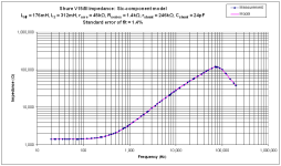
That is correct and measurable. The simple inductance and resistance model quoted by cartridge manufacturers is wrong. Cartridge inductance needs to be modelled as an inductance in series with L//R. All in series with resistance, ideally also with shunt resistance and capacitance. A six-component model, not two. Later Shures (V15/III onwards) in particular show a very low proportion of inductance at high frequency (<30% of the 1kHz value), whereas recent Ortofons are nearer to 70%.Iron core coils usually show a decreasing inductance and increasing series resistance with frequency due to eddy-current losses. Your example really shows that.
Calculated from Richard Visee's measurements:
50 kohm * sin(53 degrees)/(2 pi 20 kHz) ~= 317.77 mH at 20 kHz
6 kohm * sin(72 degrees)/(2 pi 2 kHz) ~= 454.1 mH at 2 kHz
460 mH according to some LC bridge working at an unknown frequency
500 mH according to the specifications of the manufacturer
I don't know what you mean by a high frequency, but the inductance at 20 kHz was about 70 % of the value at 2 kHz for Richard's V15-III.
I converted the imaginary part of the impedance into an equivalent series inductance, but you can also convert the imaginary part of the admittance into an equivalent parallel inductance. If I did the math correctly, the parallel inductance doesn't change much:
20 kHz: 498.21 mH
2 kHz: 502.04 mH
The resistive part varies a lot, no matter whether you look at the resistance or the conductance, although the resistance varies more than the conductance, see post #17.
20 kHz: 498.21 mH
2 kHz: 502.04 mH
The resistive part varies a lot, no matter whether you look at the resistance or the conductance, although the resistance varies more than the conductance, see post #17.
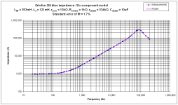
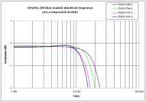
Here are my measured results and model. Note the nice tight fit, but beware that there's considerable sample variation between cartridges and channels, so the numbers are indicative, not definitive. Nevertheless, the trend is clear, and you can see from the way the impedance changes below electrical resonance that high frequency inductance in the V15 is much less than low frequency. For the benefit of the original poster, I've included the results for an Ortofon 2M. By and large, all moving magnet cartridges should be loaded with minimum capacitance to maximise the cut-off frequency of the resulting low-pass filter, but they then need a higher load resistance (often as high as 150k). The traditional upper midrange dip was a purely electrical phenomenon caused by non-ideal loading.
Attachments

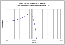
When you do that with a Shure V15-III, you get a huge response peak. Its electrical response drops to around -12 dB at 20 kHz to correct for its mechanical response, see https://www.diyaudio.com/community/threads/im-interested-in-riaa-preamps-design.425946/post-7977851 and https://www.diyaudio.com/community/threads/im-interested-in-riaa-preamps-design.425946/post-7978436 and https://www.diyaudio.com/community/threads/im-interested-in-riaa-preamps-design.425946/post-7980363
In very old German internet audio forums we can often read about a 33kHz mechanical resonance for the famous Shure MM. Furthermore, a total termination capacitance of <300pF should achieve optimum FR results.
You, we can read there!
You, we can read there!
Thank you! But am I right in thinking that this is the electrical response only? There's also the mechanical response to be considered. Of course, I've already read a lot on this forum, and Hans Polak's work (whether correct, misunderstood, or misinterpreted) made an effort to combine both. For a correct response, I think a test record is needed (something I don't have). With the help of a previous poster, I have found this for the Ortofon 2M Red.For the benefit of the original poster, I've included the results for an Ortofon 2M.
Source: Audiosciencereview.com
210 pF seems a too high load capacitance.
I've considered electrical response only. Best electrical response for a 2M Blue is 100pF//68k, so that's probably correct for the Red as well.
Returning to the Shure V15/III, it's clear that its transducer mechanical response is far from flat because neither is its electrical response with recommended loading. I'm quite prepared to believe it has a fierce ultrasonic mechanical resonance.
I think it's significant that the Audio Technica VM520 gives a very nearly perfect electrical response with the manufacturer's loading of 100pF to 200pF in parallel with 47k, suggesting that their transducer's mechanical response is nearly flat. Most modern cartridges seem to give a nearly flat electrical response with manufacturer's recommended loading, but reducing capacitance always extends bandwidth.
My point is that cartridge resistance is unchanging but that its inductance needs to be split into two parts to account for core losses.
Attachments
What definition for cartridge resistance do you use? I simply mean the real part of the cartridge impedance, no matter what its physical cause may be.
Questions for the group,
AFAIK the Shure type 3, 4, 5, Ultra, etc. have laminated cores which should theoretically reduce core losses. Have any of you observed/measured/calculated an effect from this design detail? Have any other mfr's used laminated cores? What are MC coil forms and step-up transformer cores made of?
Ray K
If I did the math correctly, the parallel inductance doesn't change much:
20 kHz: 498.21 mH
2 kHz: 502.04 mH
tan delta = Rs /(omega * Ls)
Lp = Ls * (1 + (tan delta)^2)
mostly in the H range 120Hz,460 mH according to some LC bridge working at an unknown frequency
i.e.
it is the Lp value /number !
Dear Marcel,
what is exatly your term G* ?
G is normaly 1/R in [A/V] ==> Siemens

Where is the hidden C, the capacitive effect of the wire windings? How thin and how long is the wire, how many winding layers are there, etc. pp.
what is exatly your term G* ?
G is normaly 1/R in [A/V] ==> Siemens
Where is the hidden C, the capacitive effect of the wire windings? How thin and how long is the wire, how many winding layers are there, etc. pp.
The star is a reference to a footnote that says it is calculated from measured data. G is simply the real part of the measured admittance, so the real part of the reciprocal of the measured impedance. I don't need to know how big the wire capacitance is, I just calculate G from the measured impedance magnitude and phase. Your schematic in post #37 has the losses spread over two places, while I transfer them to either a frequency-dependent resistance R = Re(Z) or a frequency-dependent conductance G = Re(1/Z).
cartridge resistanceMy point is that cartridge resistance is unchanging but that its inductance needs to be split into two parts to account for core losses.
is DCR
Rdc of the entire coil.
Your replacement circuit is flawless.
The real component of our equivalent twopole does not change, i.e. it does not change at the point under consideration, i.e. at jOmega ... and you know all this perfectly well. The pure wire resistance does not change, it is constant if T=const.What definition for cartridge resistance do you use? I simply mean the real part of the cartridge impedance, no matter what its physical cause may be.
The constant perpetuation of the /this topic is very tiring.
HBt.
ok, thx,(...) I just calculate G from the measured impedance magnitude and phase.
so your G* is 1/Re(Z)
a just for fun number /value !
There is a knot hidden somewhere, please untie it.
1/51.5e-6 is 19.42kOhm not your 1k854Ohm !?
- Home
- Source & Line
- Analogue Source
- Load capacitance on MM cartridge